Automate fluid flow control system

Active Publication Date: 2008-03-27
ADVANCED MODERN TECH
View PDF14 Cites 15 Cited by
  • Summary
  • Abstract
  • Description
  • Claims
  • Application Information

AI Technical Summary

Benefits of technology

[0017]Another object of the present invention is to provide an automate fluid flow control system, wherein the conventional fluid system does not require to alter its original structural configuration in order to incorporate with the present invention. Therefore, the user is able to mechanically-manual

Problems solved by technology

However, the solenoid valve has several common drawbacks.
It is one of the common problems to cause a failure of operation of the solenoid operated valve.
Thus, the maintenance cost of the solenoid operated valve is higher than that of the conventional manual operated valve.
In addition, the structural design of the solenoid operated valve is different from that of the manual operated valve.
In other words, when the fluid system is incorporated with the solenoid operated valve, the fluid system will lose the mechanical-manual operated feature.
Therefore, there is no alternative to operate the water flowing cycle when the solenoid operated valve has failed to operate.
In order to install the solenoid operated valve into the conventional fluid system, the mechanical-manual operating mechanism of the valve must be totally removed, which is a waste of resources in order to incorporate with the solenoid operated val

Method used


Image

  • Automate fluid flow control system
  • Automate fluid flow control system
  • Automate fluid flow control system

Examples


Example

[0062]As shown in FIG. 7, an automate fluid control system of a second embodiment illustrates an alternative mode of the first embodiment of the present invention, wherein the automate fluid control system of the second embodiment is incorporated with the faucet 1′. It is worth to mention that the automate fluid control system of the second embodiment has the same structural configuration of the first embodiment such that the second embodiment illustrates the automate fluid control system incorporates with the built-in sensor type faucet 1′. In other words, the operation of the second embodiment is the same as the operation of the first embodiment.

[0063]The automate fluid control system comprises a valve body 10′ having a fluid inlet 11′, a fluid outlet 12′, and a fluid chamber 13′ communicating between the fluid inlet 11′ and the fluid outlet 12′, wherein a flow of fluid passes from the fluid inlet 11′ to the fluid outlet 12′ through the fluid chamber 13′. Accordingly, since the au...


PUM


Abstract

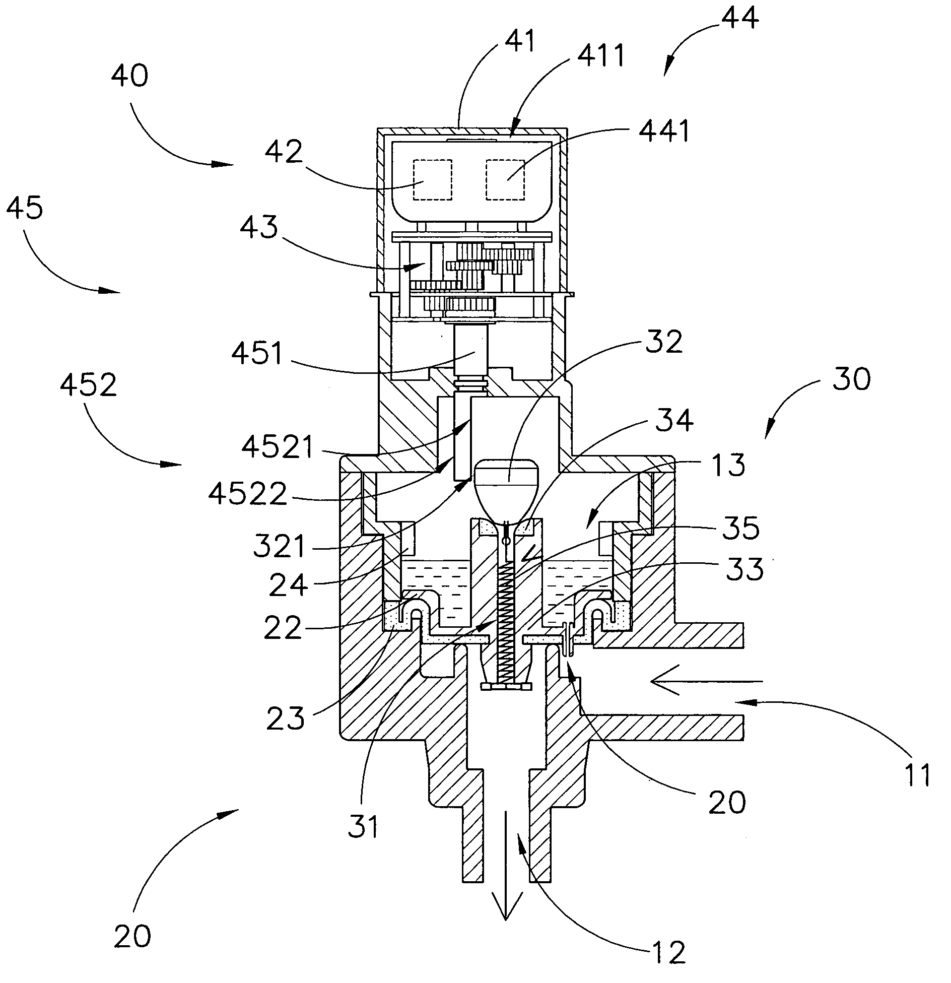
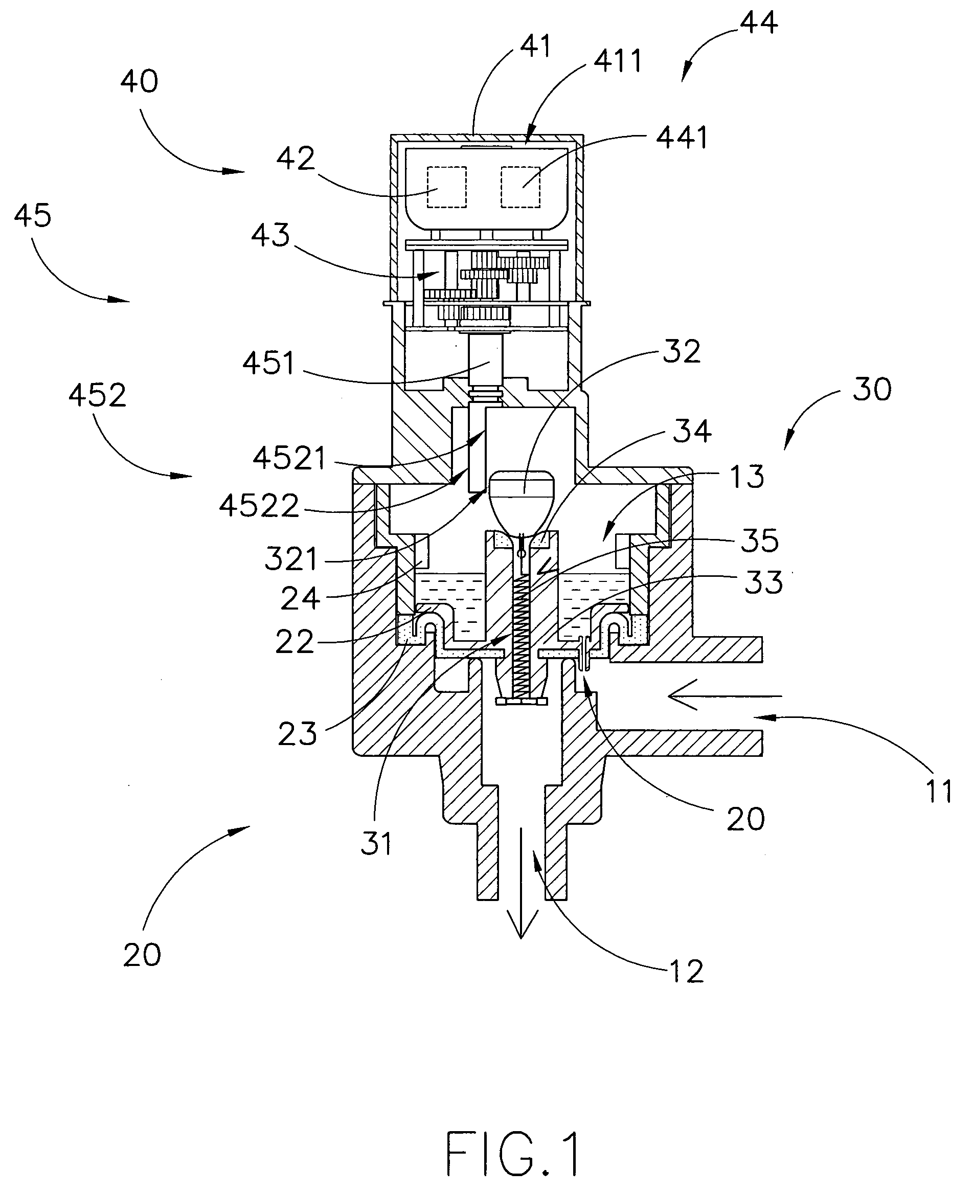
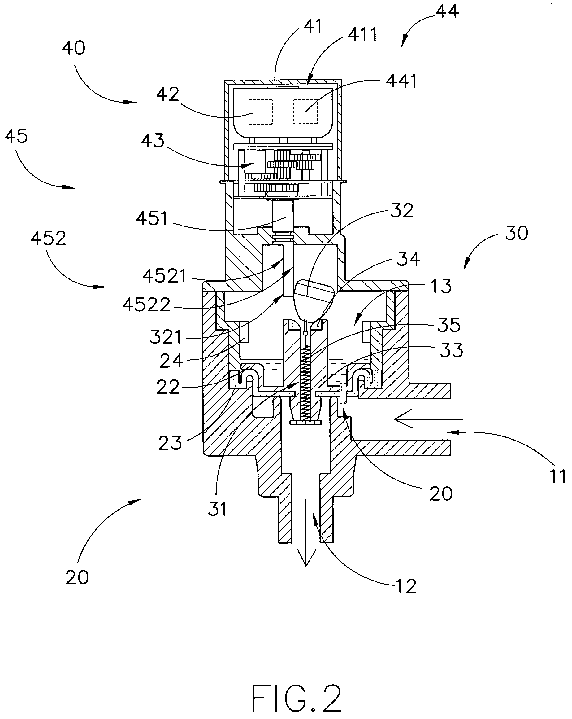
An automate fluid flow control system includes a valve member for being sealedly disposed within a fluid chamber to seal a flow of fluid flowing from a fluid inlet to a fluid outlet, a relief valve having a fluid passage extended along the valve member for communicating the fluid chamber with the fluid outlet and including a valve stopper sitting on a top opening of the fluid passage to sealedly close the fluid passage, and a powering assembly including an actuator to move the relief valve between a closed position that the valve stopper is sealedly retained to close the fluid passage and an opened position that the actuator drives the valve stopper to unseal the fluid passage for releasing a pressure within the water chamber to allow the fluid passing to the fluid outlet.

Description

BACKGROUND OF THE PRESENT INVENTION [0001]1. Field of Invention[0002]The present invention relates to a fluid system, and more particularly to an automate fluid flow control system, which allows to automatically control a flow of fluid through a fluid system, such as a faucet system, a toilet system, a showering system, or even a water piping system.[0003]2. Description of Related Arts[0004]A fluid system, such as a toilet system, a faucet system, or a water piping system, generally comprises a fluid inlet, a fluid outlet, and a fluid valve device operatively communicating between the fluid inlet and the fluid outlet to control the fluid flowing from the fluid inlet to the fluid outlet.[0005]For example, a manual operated valve device, using for in the faucet system or the toilet system, comprises a valve body communicating the water inlet with the water outlet, a relief valve disposed in the valve body for blocking the water flowing from the water inlet to the water outlet, and an ...

Claims


Application Information

Patent Timeline
IPC IPC(8): F16K31/04
CPCF16K31/404E03C1/055Y10T137/0318Y10T137/0324Y10T137/7722Y10T137/7758Y10T137/86413
Inventor MAERCOVICH, JORGE
Owner ADVANCED MODERN TECH
Why Eureka
Try Eureka