
Double-Pipe geothermal water circulating apparatus

a geothermal water and circulating technology, applied in the direction of domestic cooling apparatus, heat pumps, lighting and heating apparatus, etc., can solve the problems of inability to remove an operational problem, significant energy loss, soil contamination,

Inactive Publication Date: 2008-03-27
UEYAMA HIROAKI
View PDF17 Cites 40 Cited by
  • Summary
  • Abstract
  • Description
  • Claims
  • Application Information

AI Technical Summary

Benefits of technology

[0015]This invention is aimed at providing a double-pipe geothermal water circulating apparatus that can be continuously used even if a plurality of strainers in contact with an aquifer is clogged, and also cause no exhaustion of water in a well or ground subsidence by smoothly returning geothermal water collected from the aquifer.
[0018]According to the present invention, this apparatus can be continuously used even if a plurality of strainers in contact with an aquifer is clogged, and also cause no exhaustion of water in a well or ground subsidence by smoothly returning geothermal water collected from the aquifer.

Problems solved by technology

However, the invention of the first embodiment disclosed in the above Japanese Unexamined Patent Publication could cause the leakage of a medium liquid due to damage to the geothermal source collecting casing from corrosion and earthquake, resulting in soil contamination.
Additionally, since the geothermal source collecting casing geothermally heats the medium liquid from a side wall thereof, energy loss can be significantly found, as opposed to a conventional system for directly supplying geothermal water to an heat exchanger.
Meanwhile, the second embodiment of the above Japanese Unexamined Patent Publication is unable to remove an operational problem with strainers clogged with sediment.
More specifically, clogged strainers cannot collect and reuse geothermal water, resulting in the inability to collect the geothermal water or reuse it in the aquifer and to continuously use a well.
Solving this problem requires an arduous work of taking out the entire apparatus and high operational costs.
Subsequently, the geothermal source collecting casing and thermal insulating casing that are still under service life cannot be fully or advantageously used, and this could cause a great loss in operation.
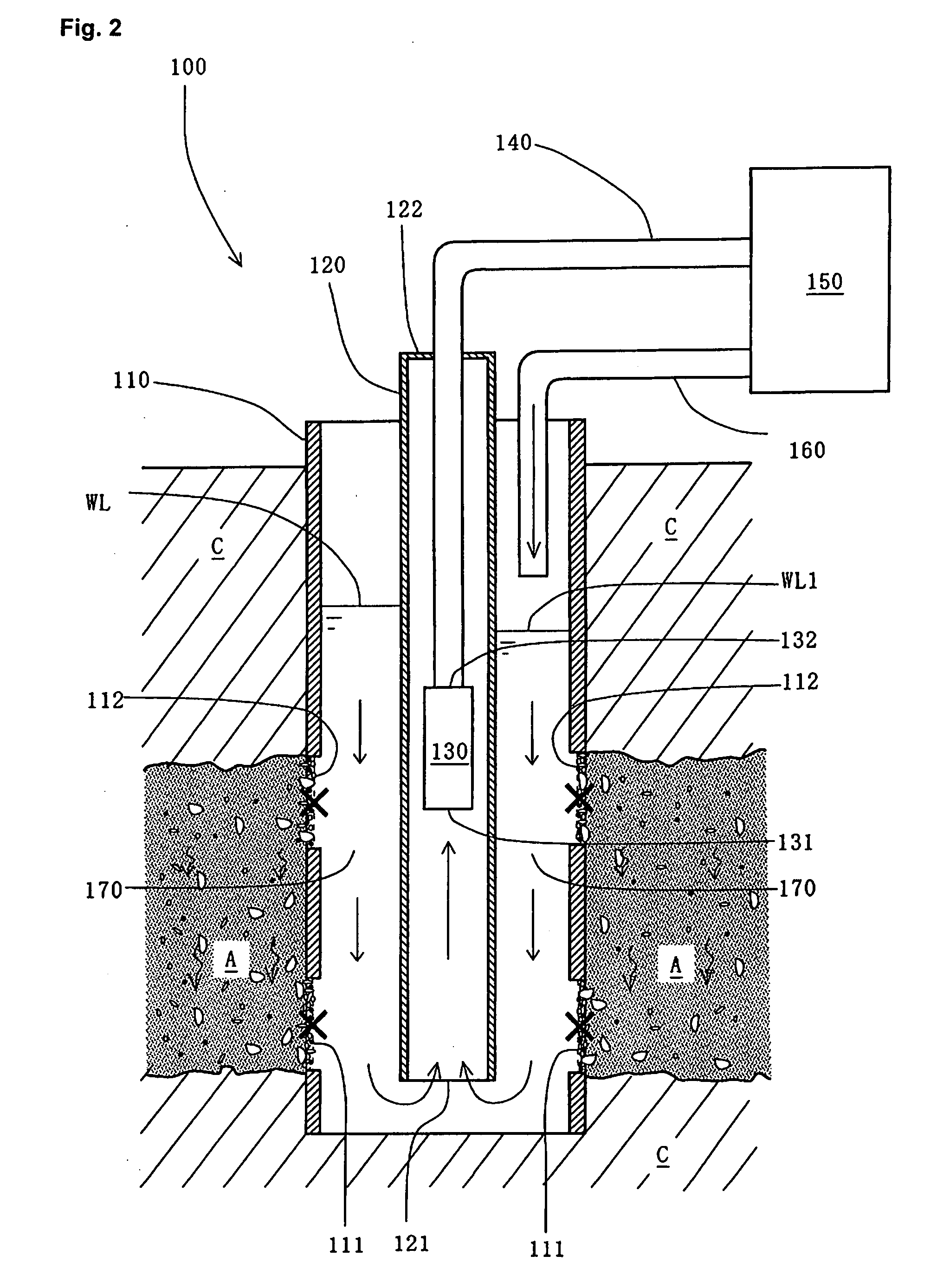
Thus, the clogging of said geothermal water returning strainer causes reused water to accumulate within the geothermal source collecting casing, thereby generating operational troubles due to liquid overflow and imbalanced flow between collected and reused geothermal water.

Method used


Image

  • Double-Pipe geothermal water circulating apparatus
  • Double-Pipe geothermal water circulating apparatus
  • Double-Pipe geothermal water circulating apparatus

Examples


first embodiment

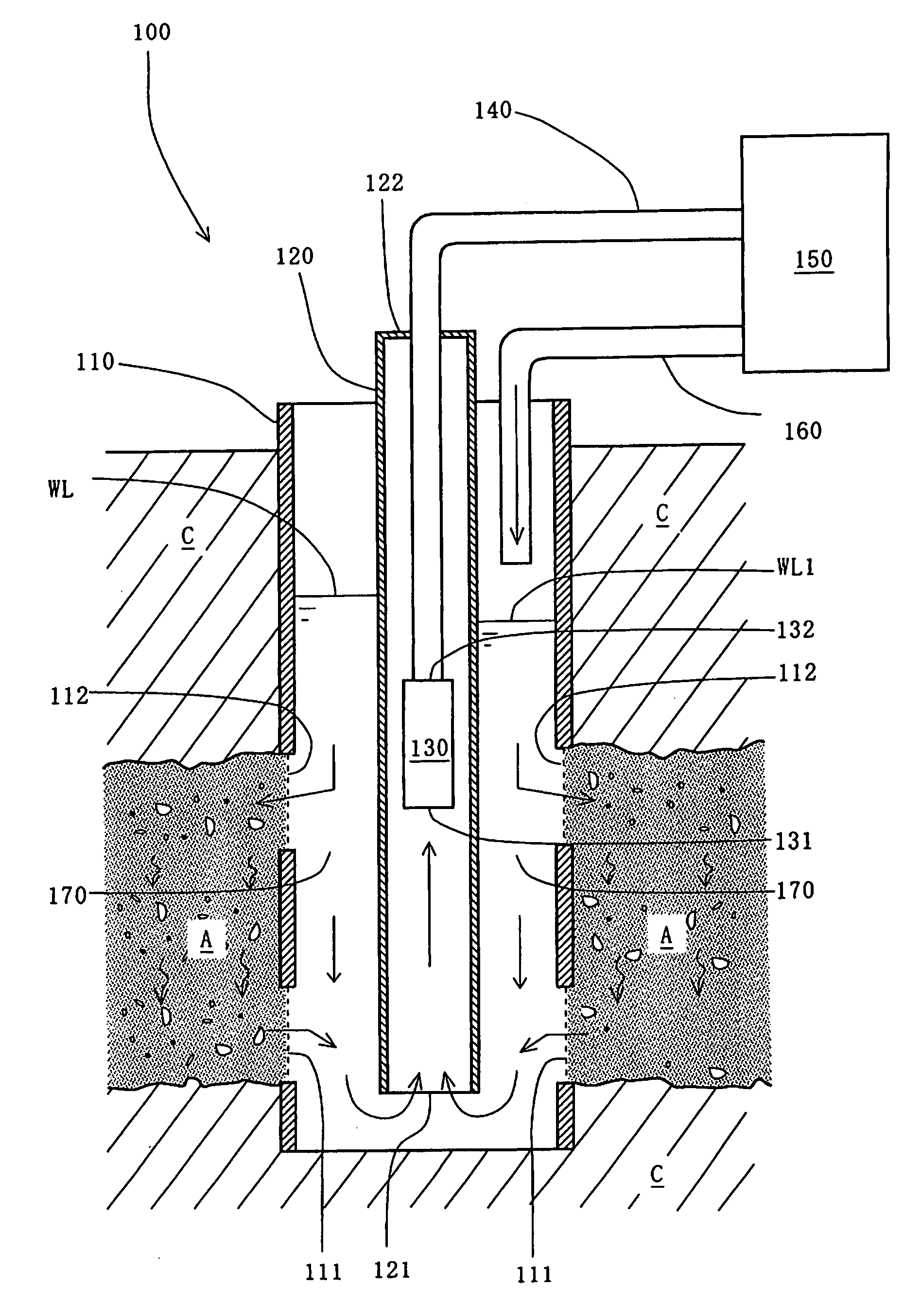
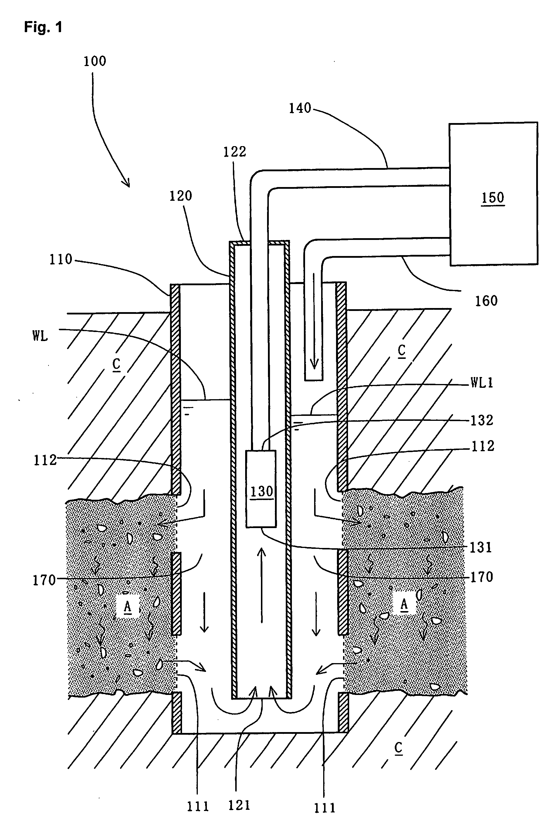
[0031]The double-pipe geothermal water circulating apparatus 100 of the first embodiment essentially comprises an outer pipe 110 for collecting geothermal water in the aquifer A and returning used geothermal water to the aquifer A, a thermal insulation inner pipe 120 inserted adjacent to a lower end of the outer pipe 110 (bottom of a well) that delivers the geothermal water above the ground in a thermal insulation, a flow channel 170 formed between the thermal insulation inner pipe 120 and said outer pipe 110, a pump 130 for pumping the geothermal water from the thermal insulation inner pipe 120, a heat source supplying force feed pipe 140 for force-feeding the geothermal water pumped by the pump 130 to an heat exchanger 150 and a heat source reusing pipe 160 for delivering the geothermal water used in the heat exchanger 150 to the flow channel 170.

[0032]Here, each component of the first embodiment will be described in detail. The outer pipe 110 collects geothermal water from the aq...

second embodiment

[0056]Next, the operations of this second embodiment will be described.

[0057]In this second embodiment, geothermal water is circulated in the double-pipe geothermal water circulating apparatus 100. Here, when the valve part 321 of the inlet 320 is opened, geothermal water in the heat source supplying force feed pipe 140 fed by the pump 130 is partially divided into the branched pipe 310 by the pressure and delivered from the inlet 320.

[0058]Accordingly, the amount of water circulating in the double-pipe geothermal water circulating apparatus 100 instantaneously declines. Unless the suction part 131 of the pump 130 comes above the running water level WL1, the geothermal water can be fed out of the double-pipe geothermal water circulating apparatus 100.

[0059]From these descriptions, geothermal water can be used as a heat source and also as a water source according to this second embodiment.

[0060]The double-pipe geothermal water circulating apparatus according to the present invention ...


PUM


Abstract

A double-pipe geothermal water circulating apparatus including an outer pipe having a geothermal water supplying strainer for infiltrating geothermal water from an aquifer and a geothermal water returning strainer for returning used geothermal water to the aquifer, a thermal insulation inner pipe composed of a thermal insulator that forms a flow channel with the outer pipe, a pump for pumping the geothermal water from the thermal insulation inner pipe, a heat source supplying force feed pipe for force-feeding pumped geothermal water to an heat exchanger and a heat source reusing pipe connected to the flow channel for returning the used geothermal water to the aquifer. Also, the double-pipe geothermal water circulating apparatus is provided therein with the flow channel from the geothermal water returning strainer to the geothermal water supplying strainer that is not separated, whereby geothermal water can flow therethrough.

Description

BACKGROUND OF THE INVENTION[0001]1. Field of the Invention[0002]The present invention generally relates to a technology for using geothermal water in an aquifer as a heating and cooling medium for exchanging the heat, and more particularly to a double-pipe geothermal water circulating apparatus that can circulate said geothermal water by returning used geothermal water to said aquifer or an above-located aquifer for exchanging the heat.[0003]2. Description of the Related Art[0004]It is generally known that the underground temperature is lower and higher than the outer temperature in summer and winter, respectively and the geothermal temperature becomes high as its observed point comes deeper. In a conventional invention, by pumping underground geothermal water in an aquifer, the geothermal water is used as a cooling medium in summer and a heating medium in winter.[0005]FIG. 7 shows a conventional type of heat exchanging system using geothermal water. In the heat exchanging system 70...

Claims


Application Information

Patent Timeline
IPC IPC(8): F25B29/00
CPCF24J3/085F24J3/086Y02B10/40Y02E10/14Y02E10/16F25B30/06F24T10/20F24T10/30Y02E10/10
Inventor UEYAMA, HIROAKI
Owner UEYAMA HIROAKI
Learn More