
Dual head soldering device

a soldering device and dual-head technology, applied in the direction of ohmic resistance heating, soldering apparatus, manufacturing tools, etc., can solve the problems of affecting the effect of the soldering process, so as to reduce the risk of burning and melting adjacent items

Inactive Publication Date: 2008-03-27
PHINETAB INVESTMENTS
View PDF15 Cites 1 Cited by
  • Summary
  • Abstract
  • Description
  • Claims
  • Application Information

AI Technical Summary

Benefits of technology

[0006]Compatible and attuned with the present invention, a device attachable to a work piece to uniformly deliver heat energy to the work piece, and reduce the risk of burning and melting adjacent items, has surprisingly been discovered.

Problems solved by technology

Holding the torch and providing the relative motion between the torch and the work piece is a source of fatigue for the user.
In many instances, the joint to be formed between the work pieces is located adjacent to other objects rendering it difficult to apply the flame uniformly around the intended joint.
Further, the items such as wood, insulation, or plastic adjacent to the pipe joint are often flammable and could be damaged by the flame of the torch.

Method used


Image

  • Dual head soldering device
  • Dual head soldering device
  • Dual head soldering device

Examples


Embodiment Construction

[0013]The following detailed description and appended drawings describe and illustrate an exemplary embodiment of the invention. The description and drawings serve to enable one skilled in the art to make and use the invention, and are not intended to limit the scope of the invention in any manner.

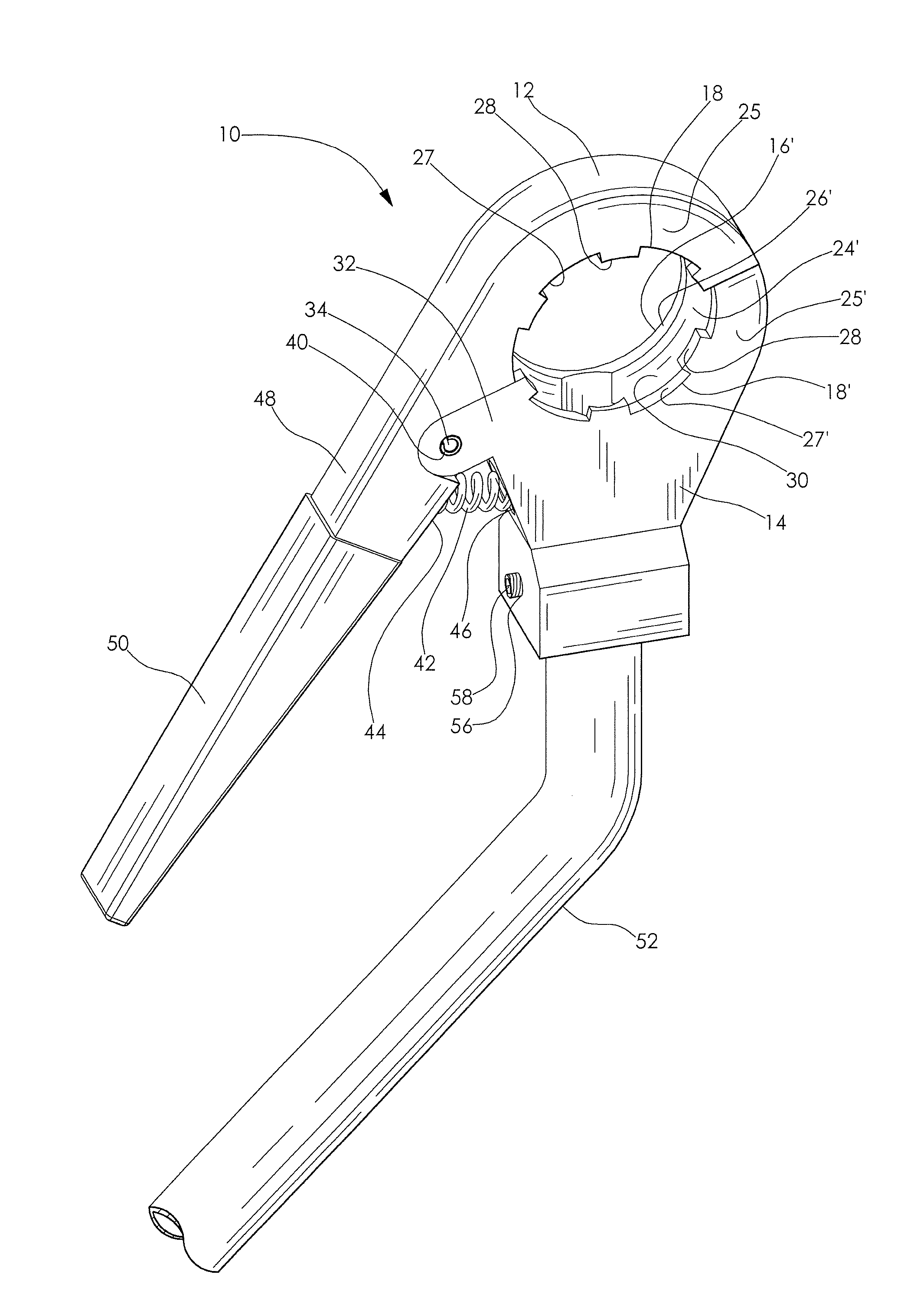
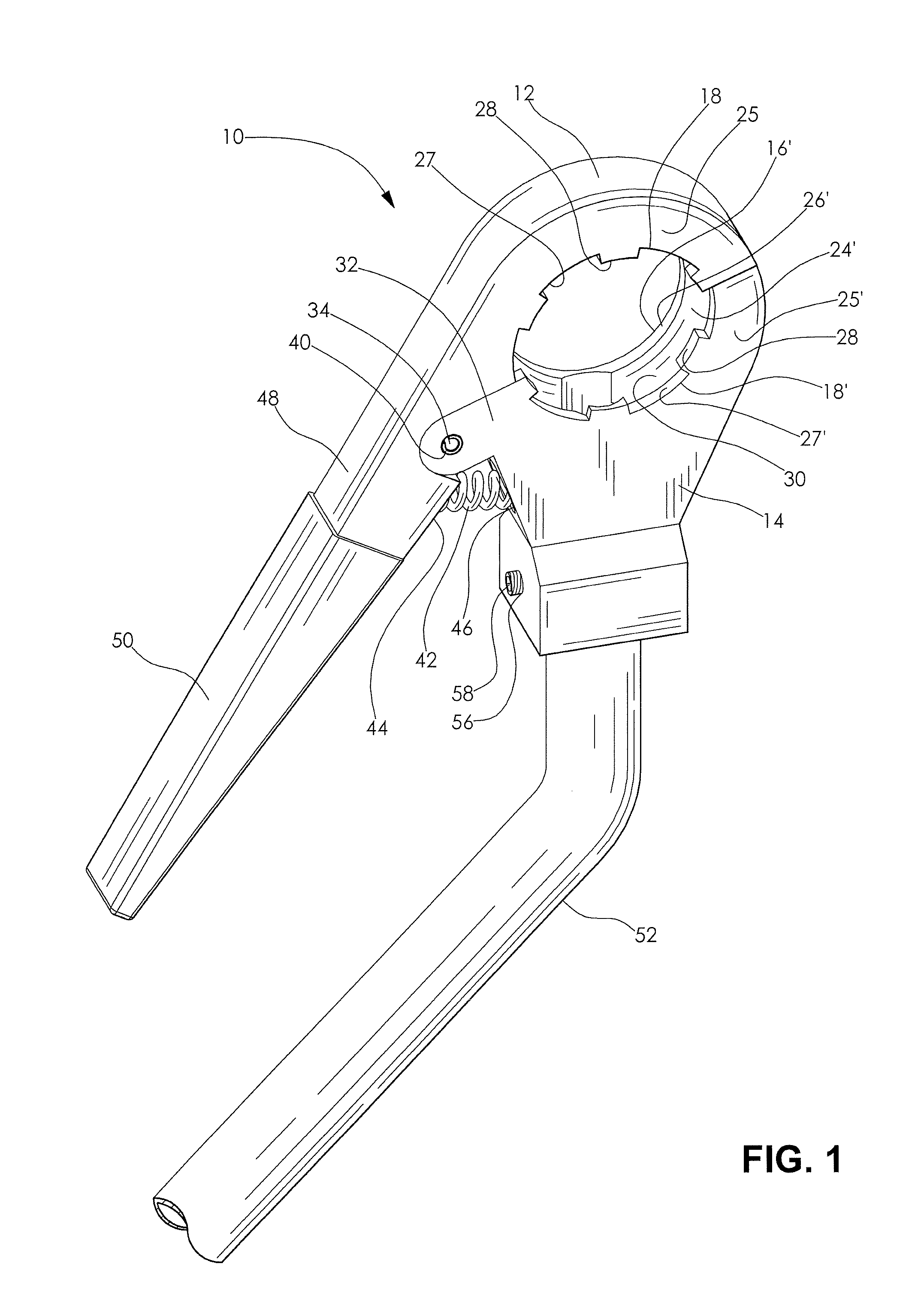
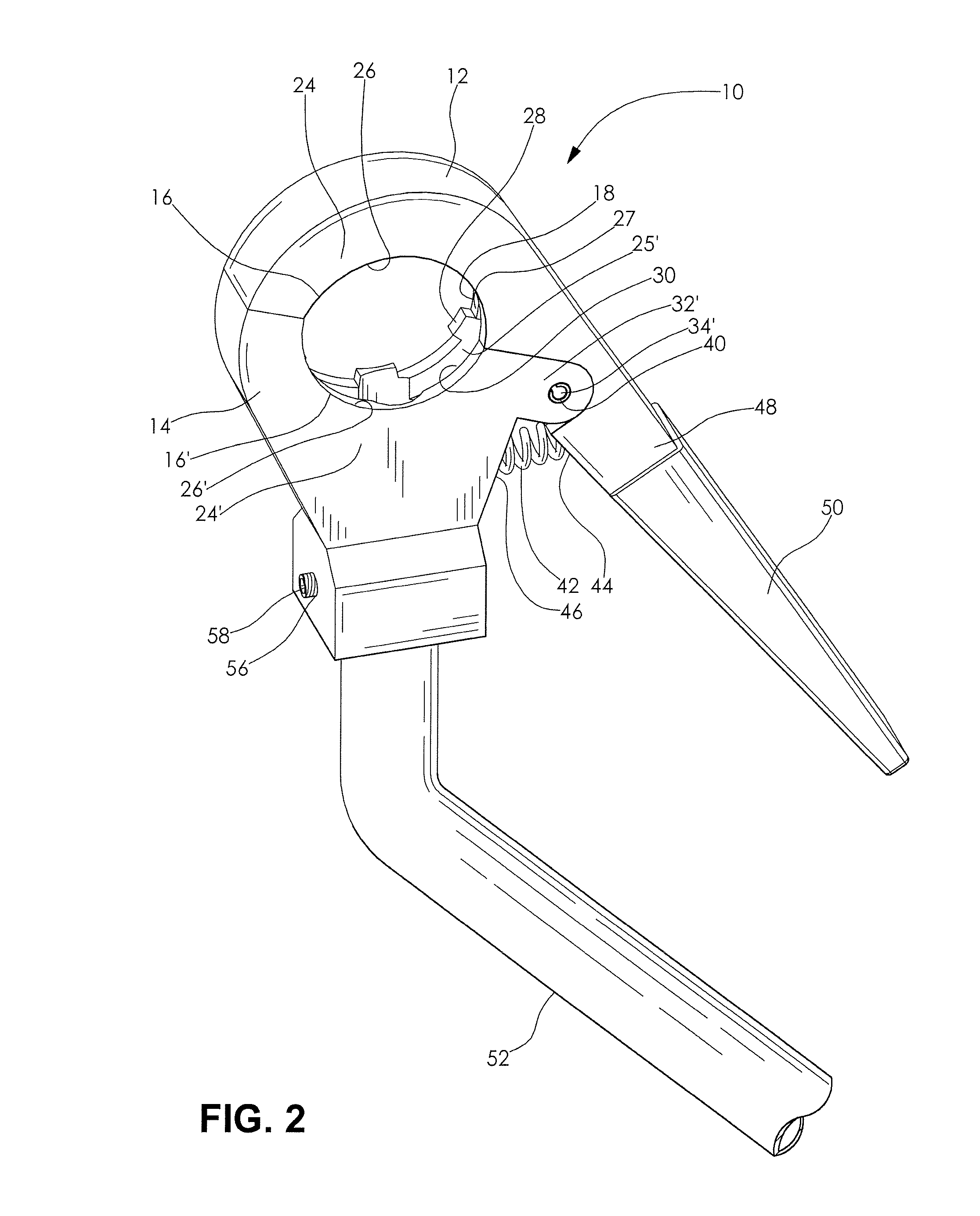
[0014]Referring to the drawings, there is illustrated in FIGS. 1, 2, and 3 a soldering device, generally indicated by reference numeral 10. The soldering device is adapted to attach to a work piece being joined to another work piece, and uniformly deliver heat energy to the ends of the work pieces while reducing the risk of burning and melting items adjacent to the work pieces.

[0015]The soldering device 10 has a pair of pivotally interconnected jaws 12 and 14. The jaws 12, 14 have a first gripping surface 16, 16′ and a spaced apart second gripping surface 18, 18′ for securely gripping the work piece between the jaws 12, 14. The first gripping surface 16, 16′ and the spaced apart second gri...


PUM


Abstract

The present invention relates to a soldering device for joining two work pieces and more specifically, a soldering device with two cooperating spring biased jaws adapted to grip a work piece to be joined to a second work piece to uniformly apply heat energy to the work pieces, and reduce the risk of burning and melting items adjacent to the work pieces.

Description

CROSS-REFERENCE TO RELATED APPLICATION[0001]This application claims the benefit of U.S. Provisional Patent Application Ser. No. 60 / 846,299 filed on Sep. 21, 2006.FIELD OF THE INVENTION[0002]The present invention relates to a soldering device for joining two work pieces. More specifically, the invention relates to a soldering device with two cooperating spring biased jaws adapted to clamp to the respective ends of two work pieces such as pipes, pipe fittings, and fixtures to be joined.BACKGROUND OF THE INVENTION[0003]The soldering of work pieces such as pipes, pipe fittings, and fixtures is typically accomplished by using a single flame gas torch. The torch is utilized to supply sufficient heat energy to the pipe joint to melt applied solder and cause the molten solder to be drawn into the joint by capillary action. A single torch requires the user to provide relative movement between the torch and the work pieces to be joined to ensure that the entire circumference of the pipe joint...

Claims


Application Information

Patent Timeline
IPC IPC(8): B23K3/04
CPCB23K3/087B23K3/043
Inventor RACHETER, PHILLIP J.
Owner PHINETAB INVESTMENTS
Learn More