Composite type energy-absorbing anti-creeper of rail vehicle

A rail vehicle and composite technology, applied in the field of composite energy-absorbing anti-climbing devices, can solve the problems of non-uniform shape and size of foam material cells, low energy-absorbing efficiency, poor controllability of compression, etc., so as to improve energy absorption. and partial load resistance, improved crashworthiness, and improved reliability

Active Publication Date: 2019-03-26
CENT SOUTH UNIV
View PDF9 Cites 8 Cited by
  • Summary
  • Abstract
  • Description
  • Claims
  • Application Information

AI Technical Summary

Problems solved by technology

[0004] (1) Cutting, planing, broaching anti-climbing device: The anti-climbing device has strict requirements on processing technology, and the melting and breaking of the tool is serious, and the reliability is poor
[0005] (2) Foamed aluminum energy-absorbing anti-climbing device: The preparation process of the foamed structural material is complicated and the cost is high, and the shape and size of the cells of the foamed material are not uniform, the arrangement is irregular, and the controllability of its compression is poor
[0006] (3) Metal profile + built-in guide structure: the controllability of compression deformation of this structure is poor, and in the process of compression and formation of wrinkles, the impact force fluctuates greatly and the energy absorption efficiency is low
[0007] (4) Thin-wall structure + built-in composite material drawer structure: this structure is heavy and has poor anti-eccentric load performance, and the anti-climber is prone to partial load failure in the initial stage of train collision

Method used


Image

  • Composite type energy-absorbing anti-creeper of rail vehicle
  • Composite type energy-absorbing anti-creeper of rail vehicle
  • Composite type energy-absorbing anti-creeper of rail vehicle

Examples


Embodiment Construction

[0035] The embodiments of the present invention will be described in detail below with reference to the accompanying drawings, but the present invention can be implemented in many different ways defined and covered by the claims.

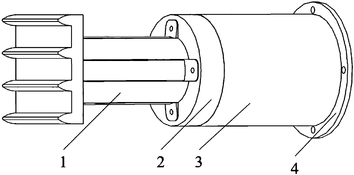
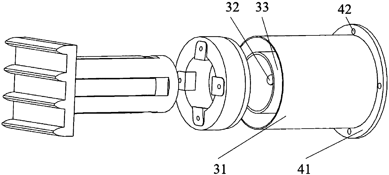
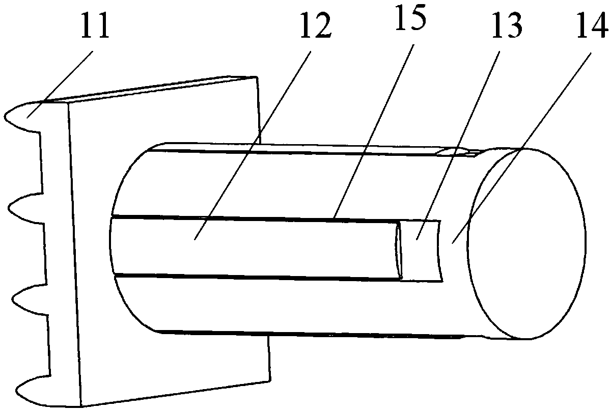
[0036] like Figure 1-Figure 7 As shown, the present invention discloses a composite rail vehicle energy-absorbing anti-climbing device, which mainly consists of an anti-climbing gear part 1, a flange assembly 2, a hydraulic cylinder body 3 and a mounting base 4, wherein the mounting base 4 and the flange assembly 2. It is sealed and installed at both ends of the hydraulic cylinder 3. The anti-climbing gear part 1 includes the anti-climbing gear 11, the piston rod 12 and the piston 14. There are four mounting bolts on the circumference of the mounting bottom plate 41 of the mounting base 4. Holes 42, the entire anti-climbing device is connected together with the vehicle chassis through the mounting holes 42.

[0037] Wherein, anti-climbing tooth 11...


PUM


Abstract

The invention discloses a composite type energy-absorbing anti-creeper of a rail vehicle. The composite type energy-absorbing anti-creeper comprises a piston rod, a flange, an inner sleeve and an outer sleeve, wherein the inner sleeve is arranged in the outer sleeve in a sealing mode; damping liquid is arranged in the inner sleeve; one end of the piston rod is equipped with a piston which can be in sliding connection to the inner sleeve; a damping hole is formed in the inner sleeve; a damping hole sealer is arranged on the damping hole; a guide hole which is in sliding connection to the pistonrod is formed in the flange; one side of the flange is fixedly connected to one end of the inner sleeve and one end of the outer sleeve; the other side of the flange is equipped with a cutting tool;and the cutting tool extends into a guide slot in the piston rod. According to the anti-creeper disclosed by the invention, a cut cutting part pushes the piston to extrude the damping liquid to absorbenergy, so that energy absorption and electric load resistance of the device are greatly improved, and therefore, the anti-creeper is high in collision force stability and energy-absorbing efficiency, and is good in energy-absorbing adjustability; and damping hole sealers of different specifications are selected, so that rail vehicle collision working conditions under different speed grades can be met, and therefore, collision resistance of the rail vehicle are improved.

Description

technical field [0001] The invention relates to the field of rail traffic buffering and energy absorption, in particular to a composite energy-absorbing anti-climber adopting hydraulic energy absorption and cutting energy absorption. Background technique [0002] With the rapid development of the rail transit industry, while improving the active safety of trains, more and more attention has been paid to the passive safety performance of rail vehicles. When the train collides at a high speed, a huge acceleration pulse will be generated, which will lead to serious damage phenomena such as arching, climbing, and overturning of the train, causing large deformation of the colliding vehicle and greatly reducing the living space of passengers. In order to reduce the damage to the car body and the injury of the occupant in the train collision accident, a large energy-absorbing and high-efficiency anti-climbing device is usually installed in the limited space at both ends of the trai...

Claims


Application Information

Patent Timeline
Patent Type & Authority Applications(China)
IPC IPC(8): B61F19/04
CPCB61F19/04Y02T30/00
Inventor 彭勇邓功勋王兴华许平高广军马闻姚曙光刘志祥
Owner CENT SOUTH UNIV
Why Eureka
Try Eureka