Coupling

a technology of coupling and coupling, applied in the field of coupling, can solve the problems of high manufacturing cost, unsuitable area use of coupling type, and complex construction, and achieve the effects of convenient use, convenient coupling and release, and simple construction

Active Publication Date: 2008-03-27
V GULDMANN AS
View PDF21 Cites 14 Cited by
  • Summary
  • Abstract
  • Description
  • Claims
  • Application Information

AI Technical Summary

Benefits of technology

[0007] The purpose of the present invention is to provide a coupling with a simple construction, where the coupling may easily be used as a secure connecting joint between different objects and readily be coupled and released.

Problems solved by technology

It is a prerequisite that the coupling is designed so that it e.g. is watertight or airtight, entailing that different packings are to be used, and the coupling is to be made in a durable material, which in turn implies that the construction is very complicated and the costs of manufacture are high, which makes this type of coupling unsuited for use in areas where two objects are to be connected / fixed without a medium having to flow between them.
As the medium is typically under high pressure and / or is flowing with great speed, the connecting and / or releasing is made difficult, as it may be difficult to move the locking ring sufficiently for the locking means to release the projecting part.
The couplings are not known either to be secure against tensile forces, as in their construction no extra safety mechanism is built in which prevents the locking means from disengaging the projecting part.
The couplings are therefore not usable when two apparatuses / units are to be coupled together, and the coupling is subjected to tensile forces.

Method used


Image

  • Coupling
  • Coupling
  • Coupling

Examples


Embodiment Construction

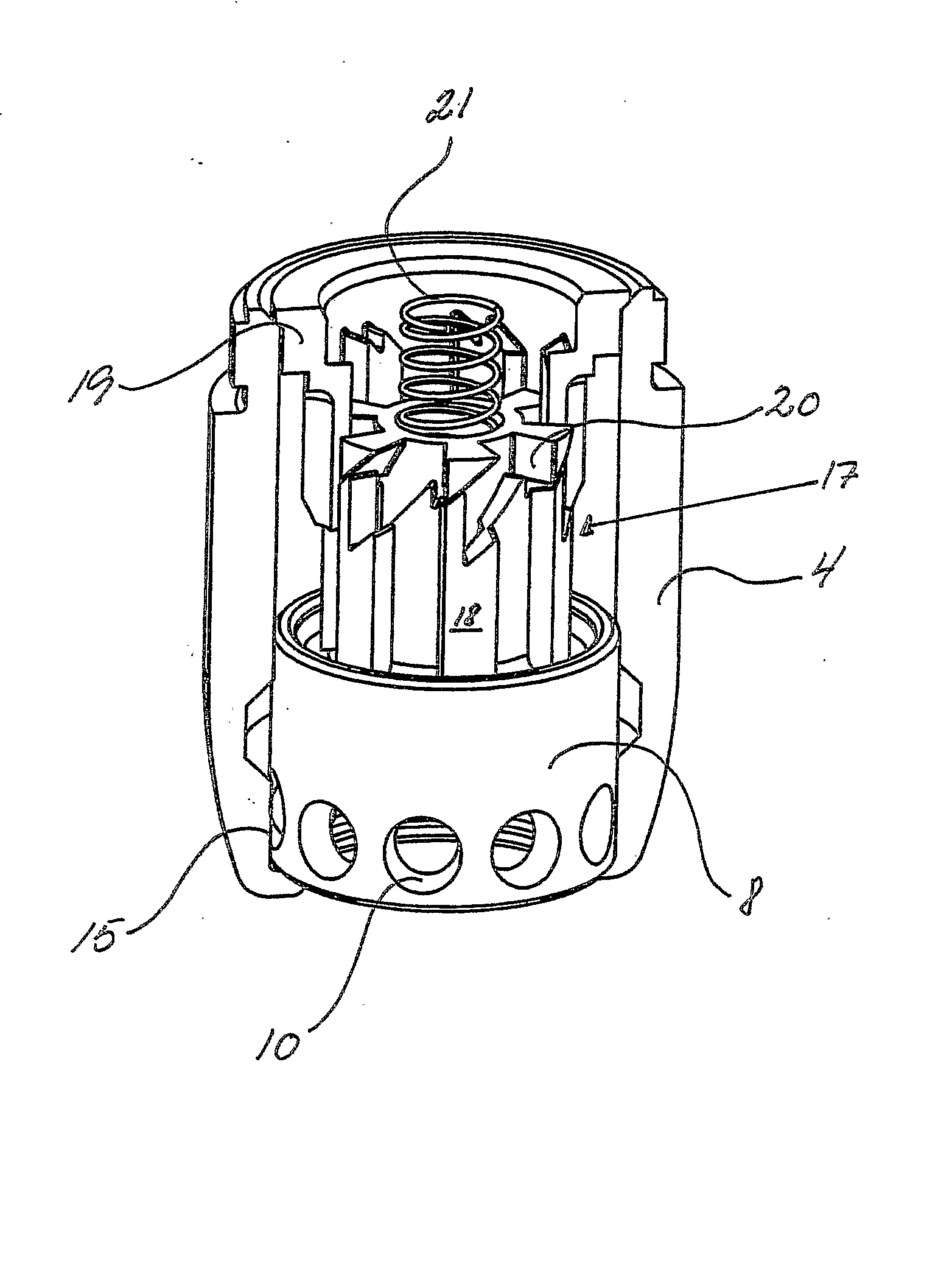
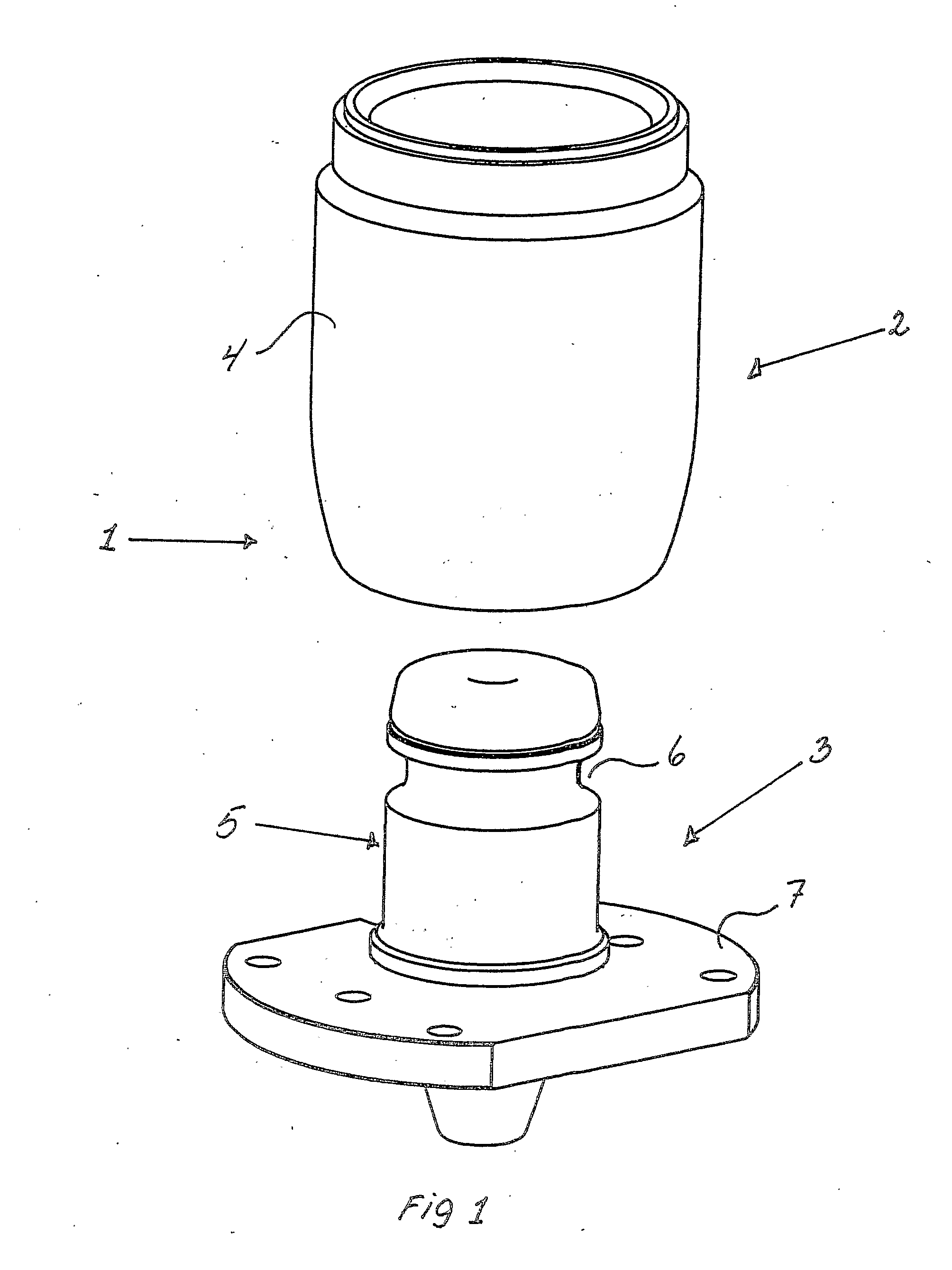
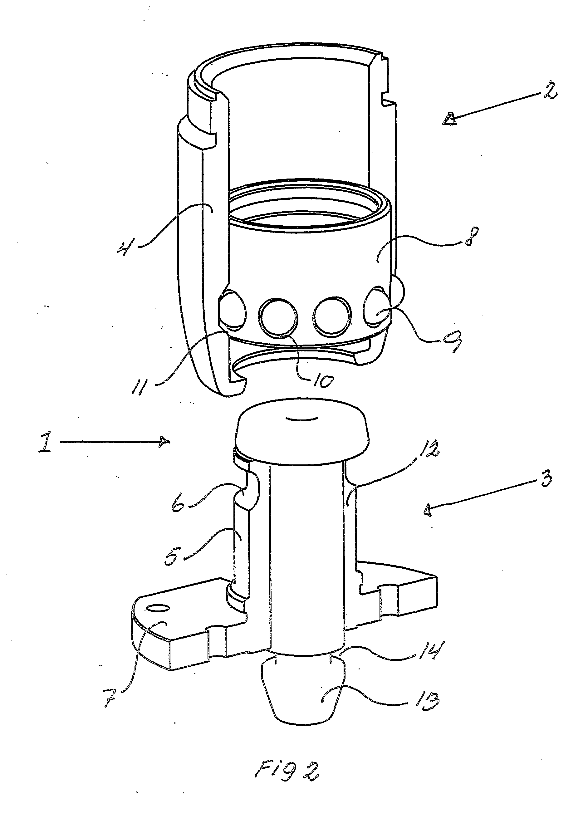
[0009] In the following, there is described a coupling which may be used primarily in the area of aiding means for e.g. transporting elderly, sick and / or heavy people in chairs / aprons which are movably fastened to e.g. rails in the ceiling. These aiding means are typically apparatuses / unit which are to be connected during transport, but which are to be separated when the person / apparatus has reached the final position. Therefore, it is to be remarked that the coupling according to the present invention may be used in other areas where it is required to secure two objects in a safe way, and that the coupling at the same time is to be easy and rapid to connect and disconnect.

[0010] The coupling according to the present invention utilises the known principle according to which the coupling comprises a first part and a second part, where the first part includes a housing in which is arranged a displaceable locking ring with locking means, and the second part includes a complementing pr...


PUM


Abstract

The present invention concerns a coupling (1) including a first part (2) and a second part (3), where the first part (2) includes a housing (4) in which is arranged a displaceable locking ring (8) with locking means (9), where the locking ring (8) in a known way is arranged for receiving and fixing a projecting part (5) of the second part (3) which is complementary to the locking ring (8), where the housing (4) in an internal cylindric surface is provided with an annular recess (11) which is arranged for accommodating the locking means (9), and where the locking ring (8) is connected with a spring-biased locking unit (17) which is arranged for moving and locking the locking ring (8) in at least two positions in the housing (4), and where the locking unit (17) includes an insert (18) which at one end is connected to the locking ring (8), and which at an opposite end is provided with a number of series of continuing, oblique teeth (23), the insert (18) having internal and external, respectively, axial projections (24, 25), a guide ring (19) surrounding the insert (18) and having internally a design which is complementary to the axial projections (25), and being provided with a number of sets of oblique teeth (26) disposed between the external projections (25), and a rotor (20) provided at one end with a number of radial teeth (28) and which at an opposite end provided with a number of stops (29) that interact with the internal projections (24), the rotor (20) seated internally in the insert (18) so that the teeth (28) interact with the oblique teeth (23, 26).

Description

FIELD OF THE INVENTION [0001] The present invention concerns a coupling including a first part and a second part, where the first part includes a housing in which is arranged a displaceable locking ring with locking means, where the locking ring in a known way is arranged for receiving and fixing a projecting part of the second part which is complementary to the locking ring, where the housing in an internal cylindric surface is provided with an annular recess which is arranged for accommodating the locking means, and where the locking ring is connected with a spring-biased locking unit which is arranged for moving and locking the locking ring in at least two positions in the housing. BACKGROUND OF THE INVENTION [0002] When assembling couplings for compressed air or water hoses, it is prior art to use couplings where there is arranged a displaceable locking ring with locking means (e.g. JP-A-09264479), which is adapted for accommodating and fixing a complementary projecting part, so...

Claims


Application Information

Patent Timeline
Patent Type & Authority Applications(United States)
IPC IPC(8): F16B21/16F16L37/22
CPCF16B21/165F16L37/23Y10S24/53Y10T24/45634Y10T403/592Y10T24/4501
Inventor BOGH-SORENSEN, OLE
Owner V GULDMANN AS
Why Eureka
Try Eureka