Radar level gauge with a galvanically isolated interface

a technology of galvanic isolation and radar level gauge, which is applied in the direction of reradiation/reflection, radio wave reradiation/reflection, measurement devices, etc., can solve the problems of limiting the total capacitance of the rlg, unable to solve the problem of distorting the measurement signal, and separating the propagation device through capacitors. complex solutions

Active Publication Date: 2008-03-27
ROSEMOUNT TANK RADAR
View PDF15 Cites 53 Cited by
  • Summary
  • Abstract
  • Description
  • Claims
  • Application Information

AI Technical Summary

Benefits of technology

[0017]In this case, the transceiver circuitry is preferably adapted to generate an analogue tank signal based on transmitted and reflected waves. The isolation interface can then be adapted to communicate this analogue tank signal from the transceiver circuitry to the pr

Problems solved by technology

A problem in this context is that the RLG will also be connected to a ground reference through the communication interface, and a ground loop circuit can develop when the different ground references are tied to different potentials.
Such a ground loop may add or subtract current or voltage from the measurement process, possibly distorting the measurement signal.
However, separating the propagation device by means of capacitors c

Method used


Image

  • Radar level gauge with a galvanically isolated interface
  • Radar level gauge with a galvanically isolated interface
  • Radar level gauge with a galvanically isolated interface

Examples


Embodiment Construction

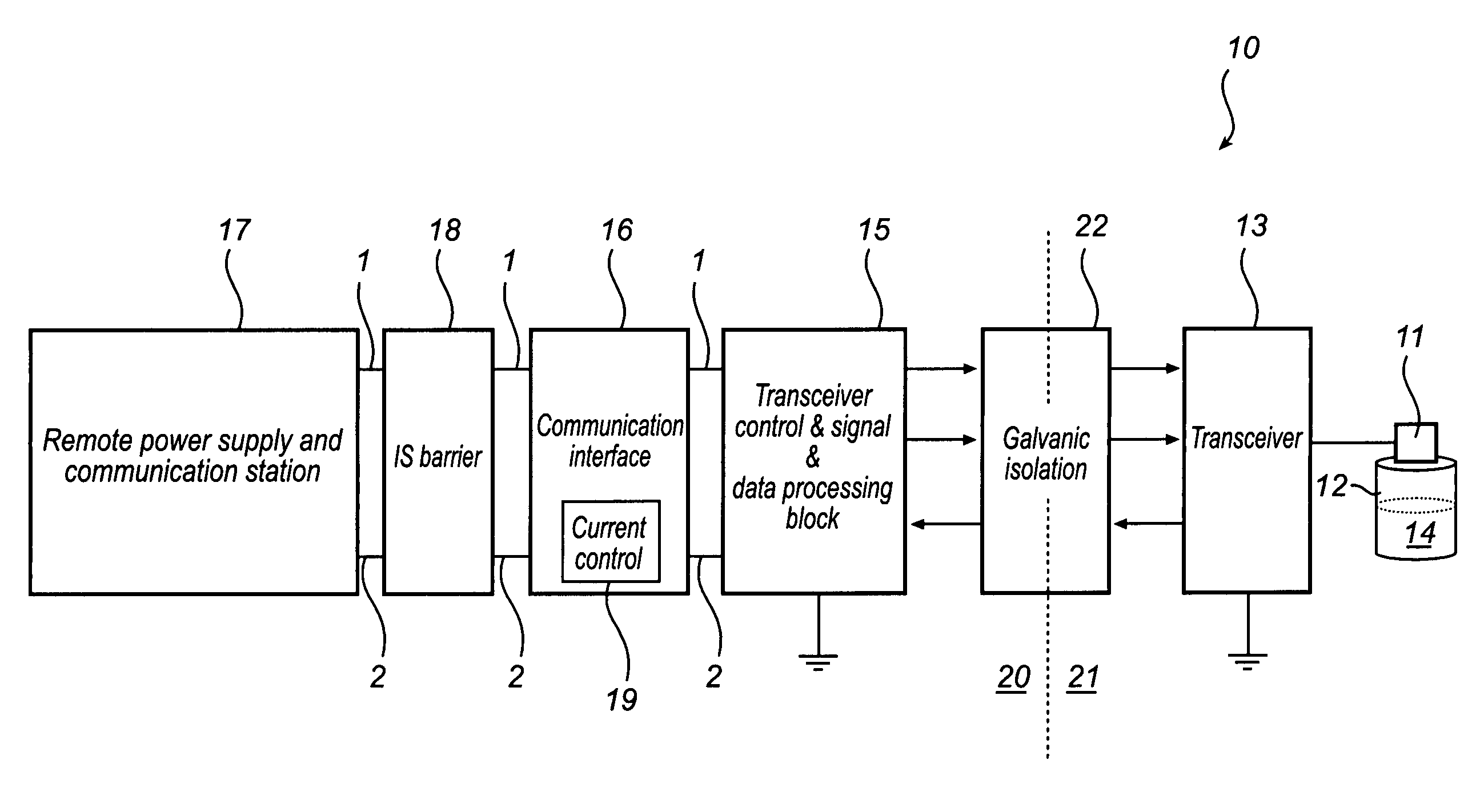
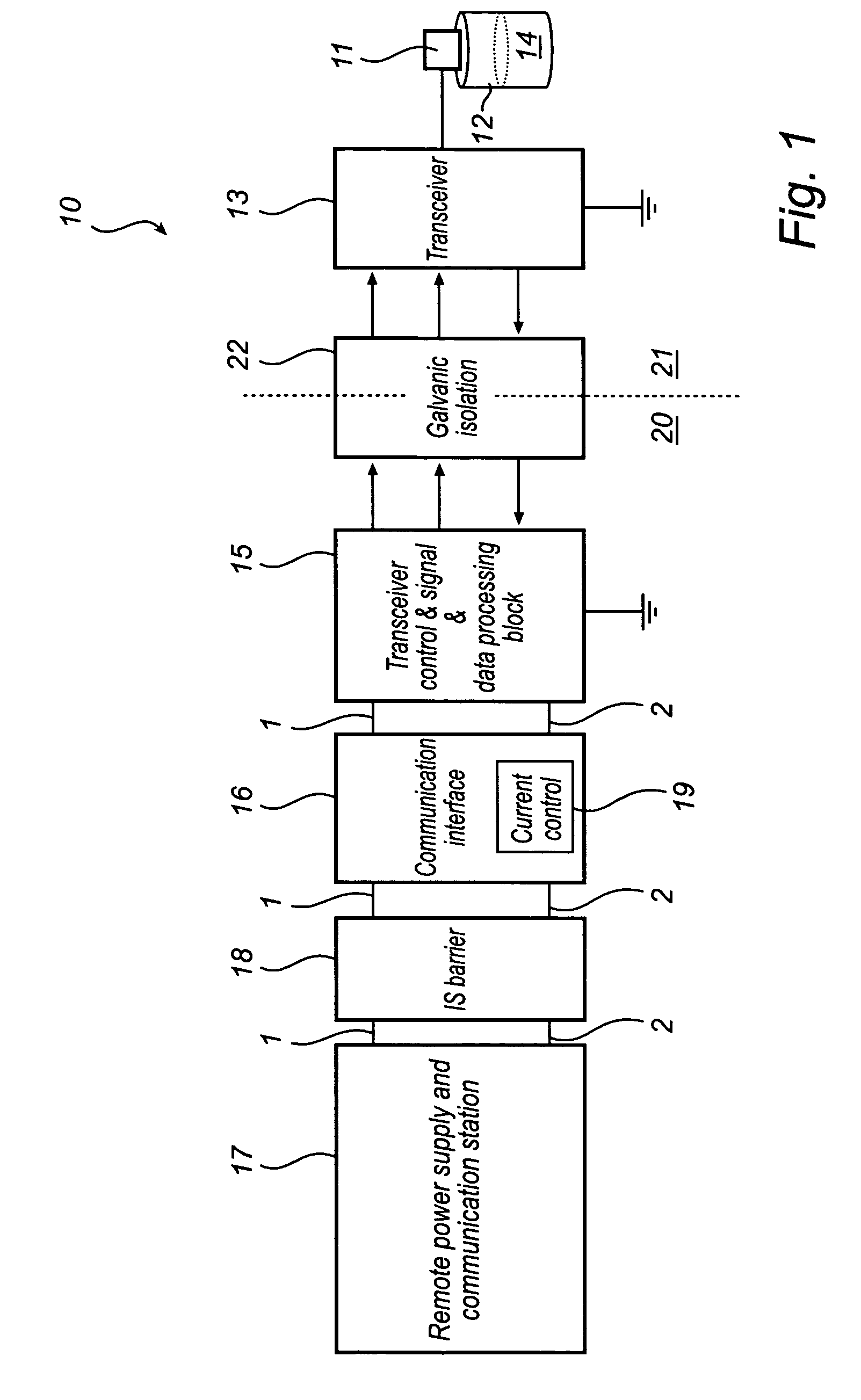
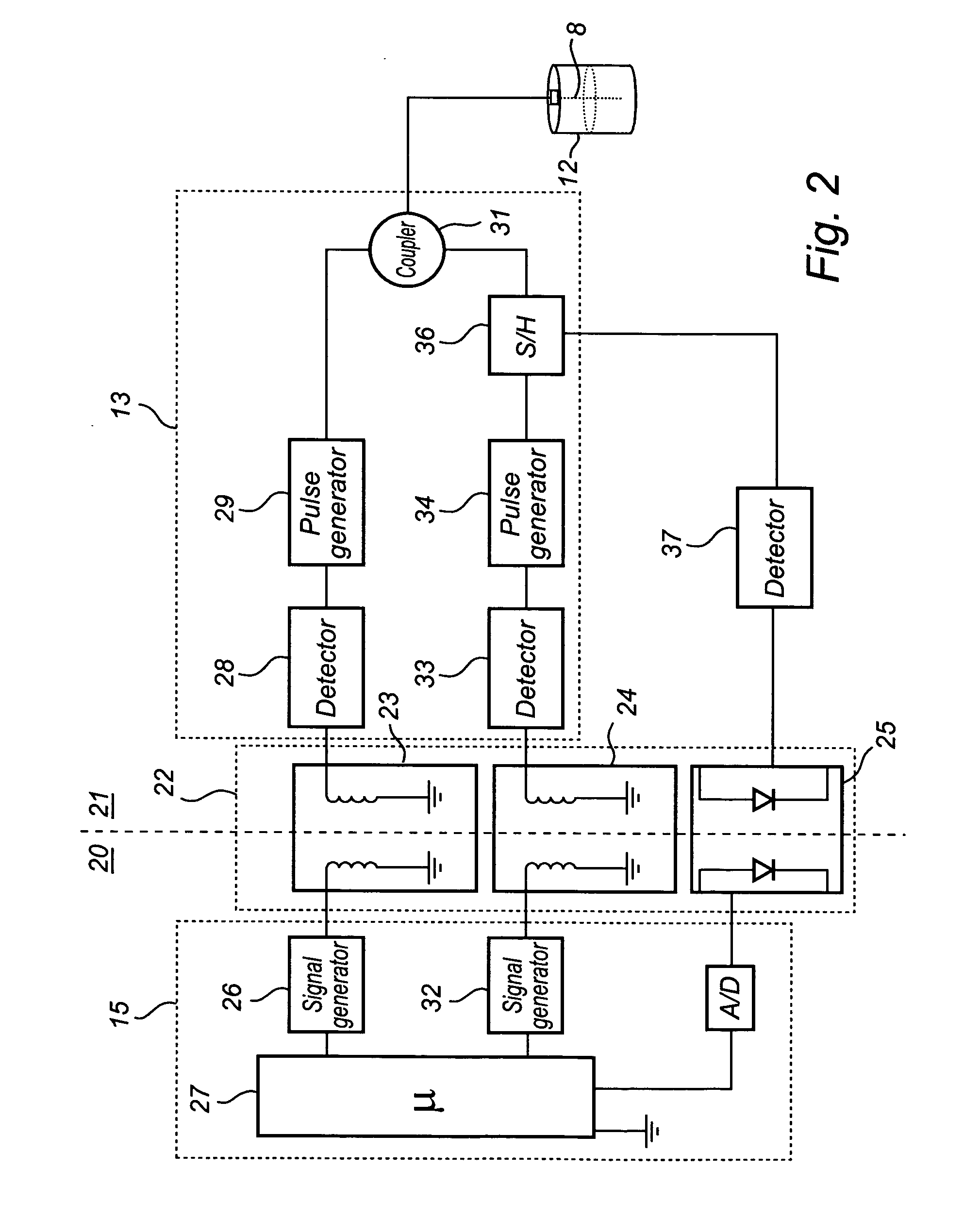
[0029]FIG. 1 shows a generalized schematic block diagram of a radar level gauge system 10 according to an embodiment of the present invention. A more detailed description of selected parts of the radar level gauge system 10 will be described below in relation to FIG. 2. The system 10 is arranged to perform measurements of a process variable such as the level of an interface between two materials in a tank 12. Typically, the first material is a liquid stored in the tank, e.g. gasoline, while the second material is air.

[0030]The radar level gauge system 10 includes a propagation device 11 extending into the tank 12, and connected to transceiver circuitry 13. The propagation device 11 is arranged to act as an adapter, transmitting electromagnetic waves into the tank 12 to be reflected by a surface of a product 14 in the tank. The propagation device 11 can be a guided wave transmission line 8 as illustrated in FIG. 2. Such a transmission line can be a flexible wire suspended between top...


PUM


Abstract

A radar level gauge using electromagnetic waves for determining a process variable of a product in a tank, comprising timing circuitry adapted to provide timing control of a transceiver, and a communication interface arranged to receive power in an intrinsically safe manner and to connect the radar level gauge externally thereof. The RLG further comprises an isolation interface arranged to galvanically isolate the transceiver from the timing circuitry and the communication interface, the isolation interface being arranged to transfer power and timing control from the timing circuitry and the communication interface to the transceiver circuitry.
According to this design, the galvanic isolation splits the radar level gauge system internally into two circuits, with no galvanic connection there between. An advantage is that this design eliminates any potential ground loops between the transceiver and the communication interface.

Description

FIELD OF THE INVENTION[0001]The present invention relates to a radar level gauge system using electromagnetic waves for measuring a level of a surface of a product in a container. More specifically, the present invention relates to a radar level gauge with a galvanically isolating interface.BACKGROUND OF THE INVENTION[0002]Radar level gauges (RLGs) are suitably used for making non-contact measurements of the level of products such as process fluids, granular compounds and other materials. An example of such a radar level gauge can include a transceiver for transmitting and receiving microwaves, a propagation device arranged to direct microwaves towards the surface and to return microwaves reflected by the surface to the transceiver, timing circuitry adapted to control the transceiver and to determine the level based on a relation between microwaves transmitted and received by the transceiver and an interface arranged to receive power and to connect the radar level gauge externally t...

Claims


Application Information

Patent Timeline
IPC IPC(8): G01S13/08
CPCG01F23/284G01S13/88G01S13/10G01S7/003
Inventor NILSSON, VALTER
Owner ROSEMOUNT TANK RADAR
Why Eureka
Try Eureka