Turbofan jet engine

a jet engine and turbocharger technology, applied in the direction of liquid fuel engines, machines/engines, efficient propulsion technologies, etc., can solve the problems of small frontal area of the engine, small supersonic wave drag, and the tendency of the above engine to make lower jet noise at takeoff, so as to reduce the exhaust velocity of the jet engine when generating the thrust required for takeoff and suppress the noise. , the effect of increasing the bypass ratio

Inactive Publication Date: 2008-03-27
JAPAN AEROSPACE EXPLORATION AGENCY
View PDF3 Cites 10 Cited by
  • Summary
  • Abstract
  • Description
  • Claims
  • Application Information

AI Technical Summary

Benefits of technology

[0021] First of all, at takeoff, the front fan and the aft fan can be operated so that external air may be introduced to the front and aft fans separately, thus the bypass airflow is increased and thereby the bypass ratio is increased as compared to when the external air is introduced to the front fan only. Accordingly, the jet exhaust velocity obtained when generating a thrust required for takeoff is reduced, and, as a result, the jet noise can be suppressed. On the other hand, during the supersonic cruise, the external air is taken into the front fan duct only. In this case, air inlet of the aft fan duct and the air outlet of the front fan duct are coupled to each other, whereby the air compressed through the front fan is introduced to the aft fan, and is further compressed through the aft fan and ej

Problems solved by technology

This means that the above engine has a tendency to make lower jet noise at take off than the engine where the fan ducts are fixed and the fans always operate in series.
Moreover, the above engine induces

Method used


Image

  • Turbofan jet engine
  • Turbofan jet engine
  • Turbofan jet engine

Examples


Embodiment Construction

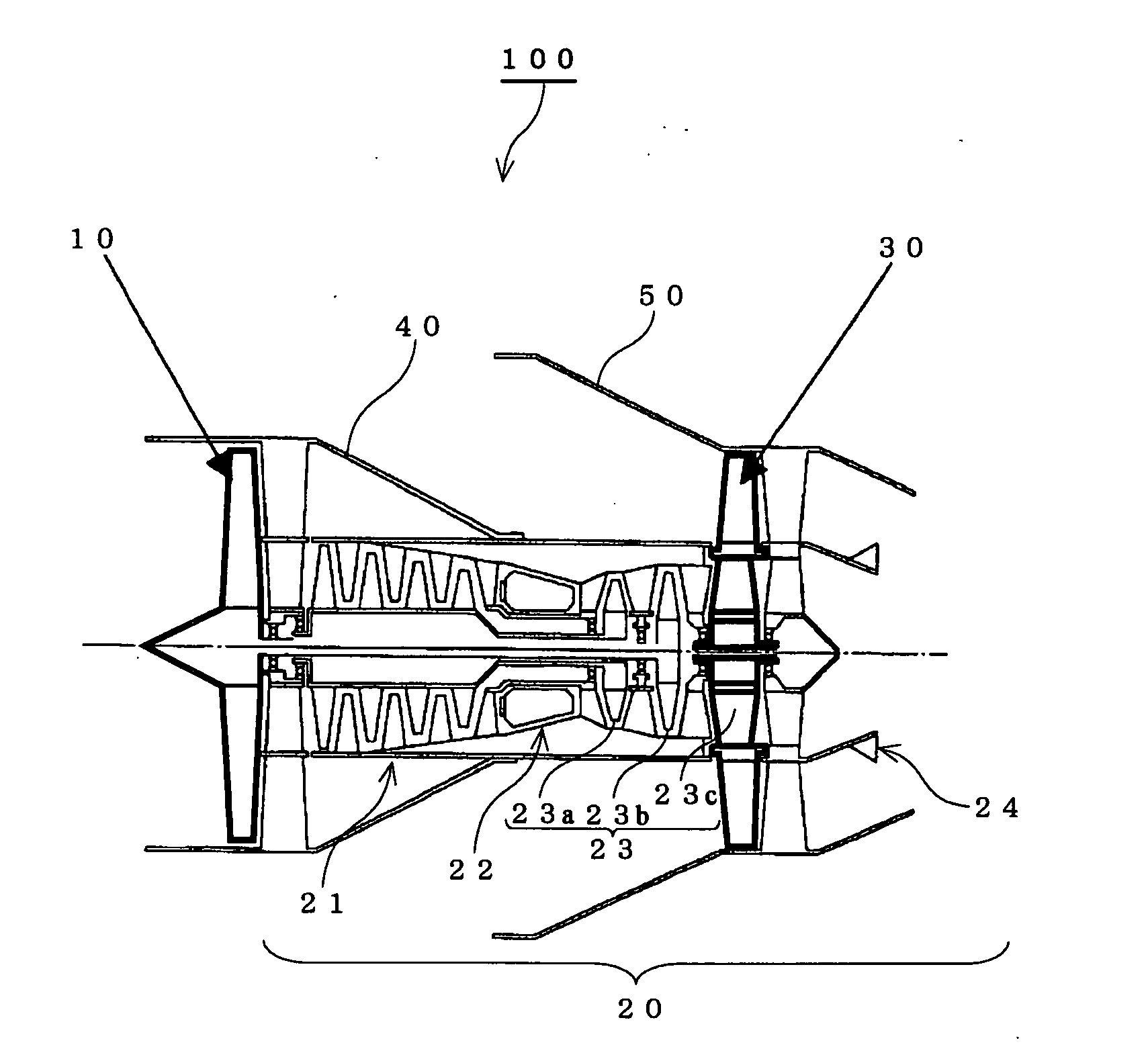
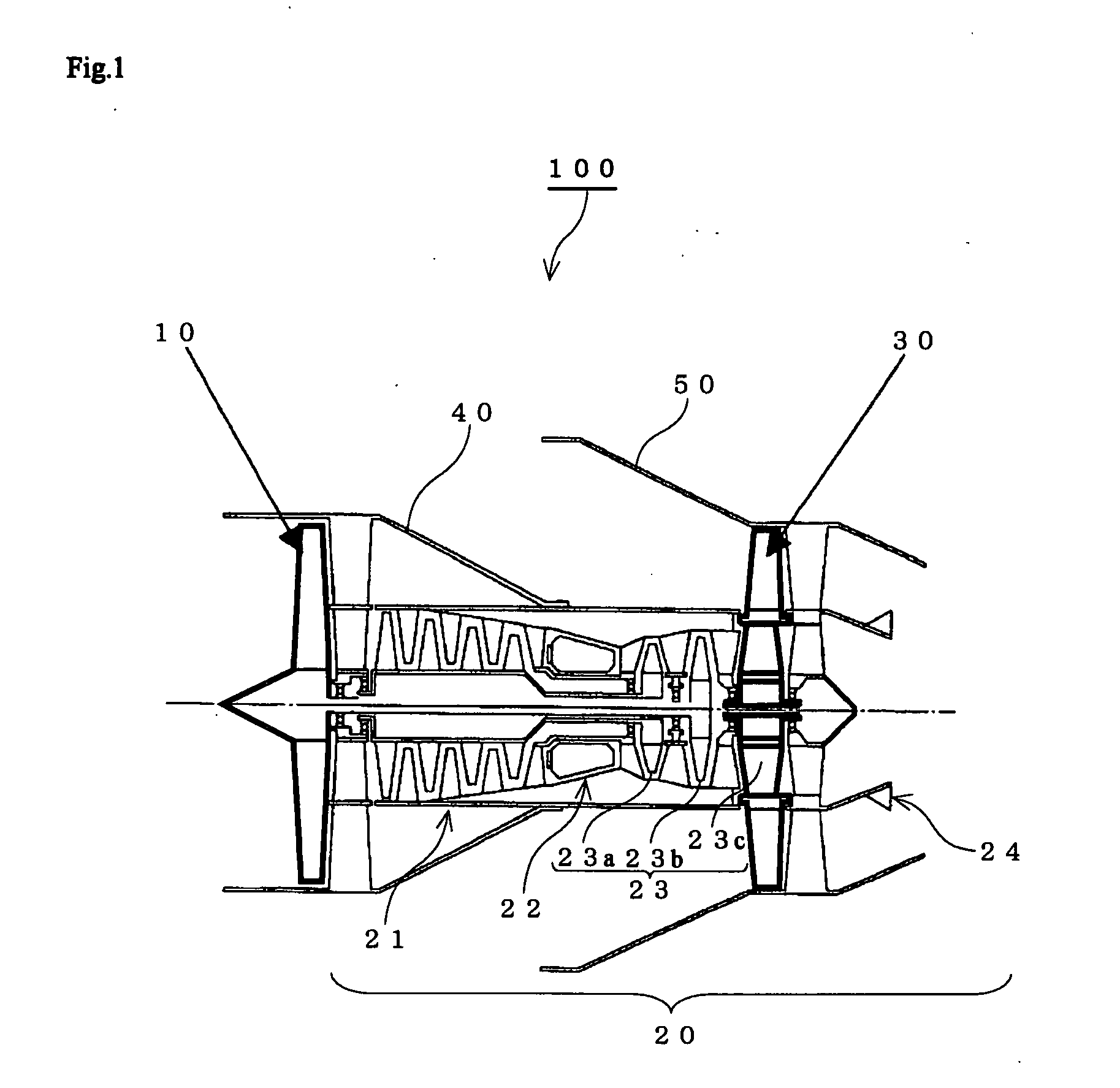
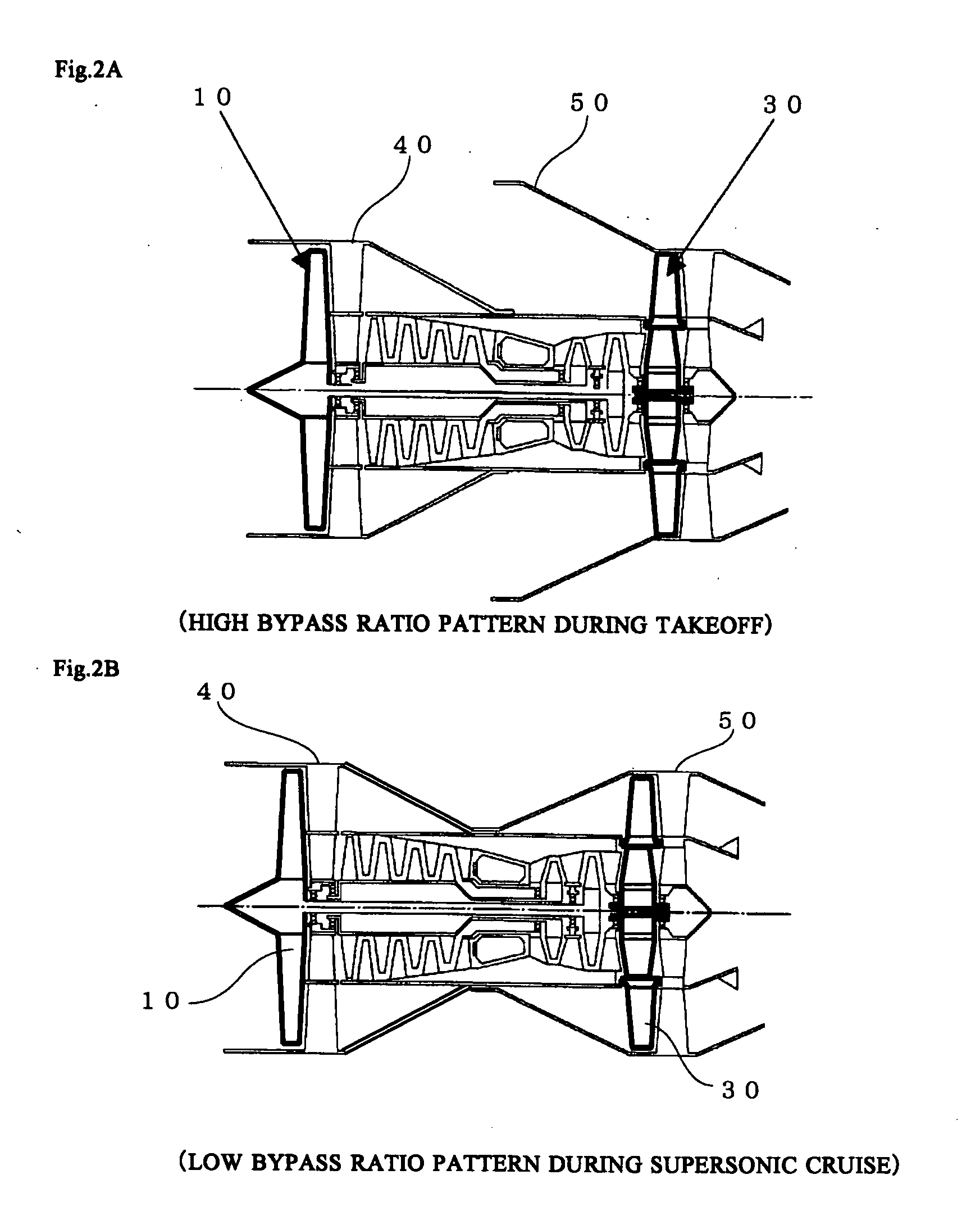
[0027]FIG. 1 is an explanatory diagram showing a substantial cross-sectional portion of a turbofan jet engine 100 of the present invention.

[0028] This turbofan jet engine 100 comprises: a front fan 10 that compresses the inlet air and supply a part of the compressed air to a core engine 20 and ejects the remaining airflow to the bypass duct; a front fan duct 40 that accommodates the front fan 10; the core engine 20 constituted by a compressor 21, a combustor 22, a turbine 23 and an exhaust nozzle 24; an aft fan 30 that compresses the received airflow; and an aft fan duct 50 that accommodates the aft fan 30 and is designed to be rotatable.

[0029] The front fan 10 is driven by a low-pressure turbine 23b disposed behind a high-pressure turbine 23a. The compressor 21 is driven by the high-pressure turbine 23a.

[0030] The aft fan 30 is disposed on an end section of an outer circumference of a turbine 23c, and driven in complete synchronization with rotation of the turbine 23c.

[0031] Re...


PUM


Abstract

To provide a turbofan jet engine for a supersonic aircraft, which enables a supersonic cruise with small additional drag due to engine installation while minimizing the jet noise at takeoff. In the turbofan jet engine, two fans, i.e., a front fan and an aft fan, are disposed, and an air inlet and an air outlet are provided on each of the front and aft fans, whereby at takeoff, air is introduced to each of the air inlets of the front and aft fans to drive the front and aft fans in parallel, and the air is then ejected from each of the outlets. On the other hand, during a supersonic cruise, an inlet of an aft fan duct is coupled to an outlet of a front fan duct, where external air is introduced only to an air inlet of the front fan duct and the air compressed through the front fan is fed to the aft fan duct and further compressed through the aft fan, and ejected from a nozzle, so that the front and aft fans are driven in series.

Description

BACKGROUND OF THE INVENTION [0001] 1. Field of the Invention [0002] The present invention relates to a turbofan jet engine, and particularly to a turbofan jet engine that is suitable for a propelling device for an aircraft that flies at supersonic airspeeds during a cruise. [0003] 2. Description of the Related Art [0004] For a supersonic aircraft, an engine with small frontal area is preferable from the view point of drag reduction because a wave drag comes out only at supersonic speed which is largely dependent on the total frontal area of the aircraft including the frontal area of the engines. On the other hand, for such an engine with small frontal area, the speed of the exhaust jet needs to be relatively high and the bypass ratio low compared to the modern high bypass ratio engines for subsonic aircraft under the condition that the same level of thrust is required. The high speed exhaust jet causes a noise problem around the airport because the noise level generally increases in...

Claims


Application Information

Patent Timeline
IPC IPC(8): F01N1/00
CPCB64D27/18B64D33/02B64D33/04B64D2033/026Y02T50/671F02K3/075F02K3/077Y02T50/44F02K3/065Y02T50/40Y02T50/60F02K3/025
Inventor YANAGI, RYOJIFUTAMURA, HISAOFUJIWARA, HITOSHI
Owner JAPAN AEROSPACE EXPLORATION AGENCY
Why Eureka
Try Eureka