Device for attaching a stator vane to a turbomachine annular casing, turbojet engine incorporating the device and method for mounting the vane

a technology for turbojet engines and annular casings, which is applied in the direction of machines/engines, liquid fuel engines, forging/pressing/hammering apparatus, etc., can solve the problems of restricted space for transverse movement, difficult access with screw-tightening equipment, and difficulty in inserting the vanes into the engine. to achieve the effect of reducing the disadvantag

Active Publication Date: 2008-03-27
SN DETUDE & DE CONSTR DE MOTEURS DAVIATION S N E C M A
View PDF5 Cites 10 Cited by
  • Summary
  • Abstract
  • Description
  • Claims
  • Application Information

AI Technical Summary

Benefits of technology

[0009] It is an object of the invention to alleviate these disadvantages and to propose a device for attaching and a method for mounting the stator vanes in an annular casing that allows the vanes to be inserted into the casing quickly and held in place in a simple way.
[0011] Advantageously, the downstream flank of the groove does not need any attached fastening means, thus making it easier to insert the vane into the casing and hold it there. A fastening means is attached only upstream of the airfoil thus allowing the vanes to be attached from the front end of the engine rather than on each side of the airfoils. The fastening means are then readily accessible to fastening tools, allowing the platform to be attached to the groove more quickly.
[0013] Advantageously, one or two screws are engaged near the upstream edge of the platform in order to hold the latter in the groove. The ease of access to the screws from the upstream side allows screw-tightening equipment to be maneuvered with ease.
[0015] Advantageously, the elastomeric material damps the deflection of the vane from the upstream to the downstream side when the air stream from the fan is being straightened by the vane.
[0018] Advantageously, the clearance is filled with a seal so as to prevent the air stream from rushing into the main stream casing.
[0021] Advantageously, this mounting method allows vanes to be mounted between the fan casing and the main stream casing with a limited number of transverse movements of the vanes with respect to the axis of the engine, and encouraging radial movements.

Problems solved by technology

It is therefore difficult to insert the vanes into the engine, particularly when engaging the vane in the groove in the fan casing, there being a restricted amount of space for transverse movement.
The platform fixing screws, positioned one on each side of the flanks of the airfoil, are engaged between two adjacent airfoils, making them difficult to access with screw-tightening equipment.

Method used


Image

  • Device for attaching a stator vane to a turbomachine annular casing, turbojet engine incorporating the device and method for mounting the vane
  • Device for attaching a stator vane to a turbomachine annular casing, turbojet engine incorporating the device and method for mounting the vane
  • Device for attaching a stator vane to a turbomachine annular casing, turbojet engine incorporating the device and method for mounting the vane

Examples


Embodiment Construction

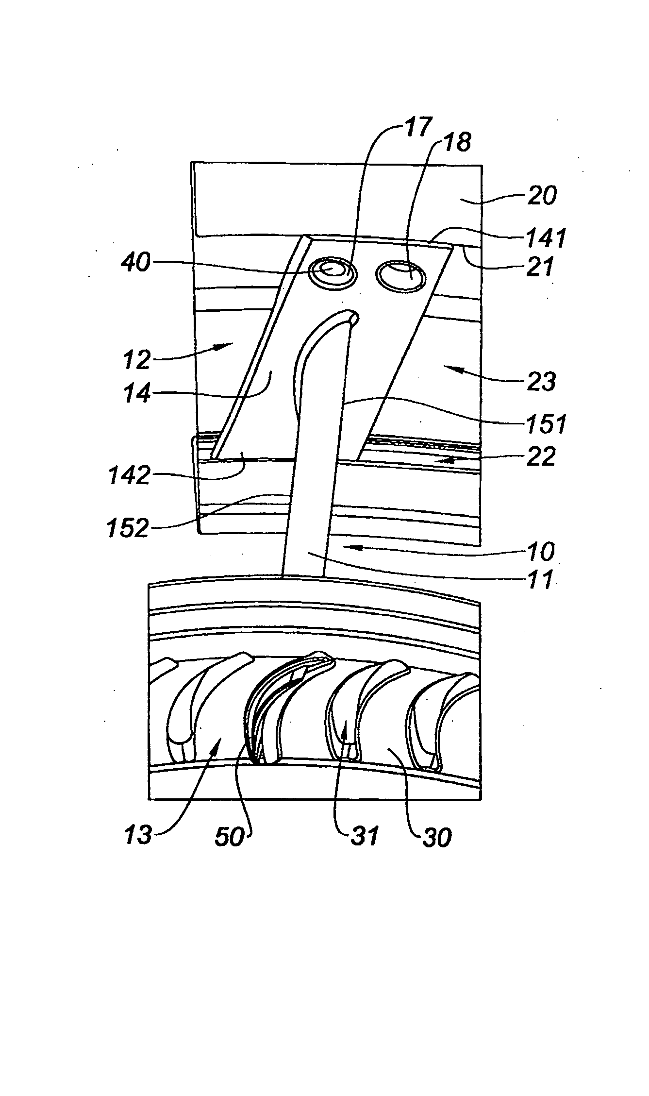
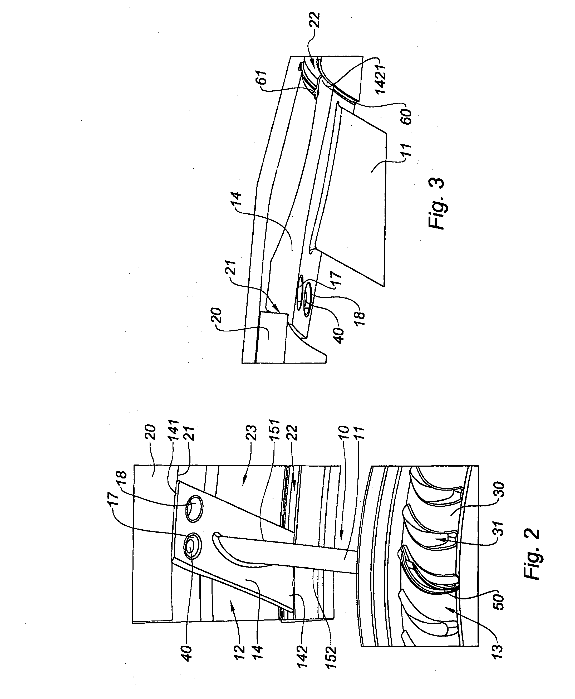
[0032] With reference to FIG. 2, a stator vane 10, or flow-straightening vane 10, here is installed in the duct of the bypass stream of a bypass turbojet engine, downstream of a fan, between a fan casing 20 and a main stream casing 30. The vane 10 comprises a tip 12 formed of a platform 14 with two edges, an upstream edge 141 and a downstream edge 142, an airfoil 11 and a root 13. The vanes 10 and the main stream casing 30 here are made of metal, but they could equally be made of a composite.

[0033] The vane 10 is positioned radially in the stream, the root 13 directed toward the axis of the engine, the airfoil 11 comprising a leading edge 151 and a trailing edge 152, the platform 14 being substantially perpendicular to the airfoil 11.

[0034] The platform 14 here is formed of a parallelepipedal block the thickness of which decreases between the upstream edge 141 and the downstream edge 142, the upstream edge 141 ending at its upstream end in a step 1411 formed on the face of the pla...


PUM

PropertyMeasurementUnit
elastomericaaaaaaaaaa
thrustaaaaaaaaaa
radial sizeaaaaaaaaaa

Abstract

The present invention relates to a device for attaching a turbomachine stator vane in an annular casing (20) of the turbomachine, the vane comprising a tip formed of a platform (14) with two edges (141, 142), one of them forming an upstream edge (141) and the other forming a downstream edge (142), an airfoil (11) and a root (13), the annular casing (20) comprising a circumferential groove (23) formed in its interior wall with an upstream flank (21) and a downstream flank (22), the vane being held by engagement of the platform (14) in the groove (23), the upstream edge against the upstream flank (21) and the downstream edge (142) against the downstream flank (22) of the groove (23), the downstream flank (22) of the groove (23) being in the form of a slot (22) opening axially in the upstream direction, the downstream edge of the platform (23) being engaged in said downstream flank (22) and a fastening means (40) being attached in order to hold the platform (14) in the groove on the upstream side, wherein the vane comprises a portion of platform (14) between the airfoil (11) and the upstream edge, this portion being pierced with a through-hole (17) designed to accept said fastening means (40).

Description

BACKGROUND OF THE INVENTION [0001] The present invention relates to the field of turbomachines, particularly bypass turbojet engines. [0002] A bypass turbojet engine for propelling transport airplanes comprises a fan, generally an upstream fan, delivering an annular air stream with a main, central, annular part, which is fed into the engine that drives the fan, and a bypass, outer, annular part which is discharged into the atmosphere providing a significant proportion of the thrust. The fan is contained in a fan casing externally delimiting the bypass stream. A main stream casing separates the primary stream from the bypass stream at a separation nose. [0003] The present invention is concerned with the attachment and mounting of stator fins or flow-straightening vanes positioned downstream of the fan. DESCRIPTION OF THE PRIOR ART [0004] The mounting of flow-straightening vanes in a turbojet engine is a technique that has been mastered for medium-sized engines, such as engines of the...

Claims


Application Information

Patent Timeline
Patent Type & Authority Applications(United States)
IPC IPC(8): F01D1/02B23P11/00F04D29/54
CPCF01D9/042F04D29/542Y10T29/49321Y10T29/49947F04D29/644Y02T50/60
Inventor BELMONTE, OLIVIER
Owner SN DETUDE & DE CONSTR DE MOTEURS DAVIATION S N E C M A
Why Eureka
Try Eureka