
Fiber reinforced thermoplastic composite panel

a thermoplastic composite panel and fiber technology, applied in the direction of glass/slag layered products, layered products, constructions, etc., can solve the problems of no mass production, no field application or demonstration, fabrication of arched profiles

Inactive Publication Date: 2008-04-03
BORAZGHI HOSSEIN
View PDF51 Cites 46 Cited by
  • Summary
  • Abstract
  • Description
  • Claims
  • Application Information

AI Technical Summary

Benefits of technology

[0010]It is a feature of the present invention to provide a fiber reinforced thermoplastic composite panel constructed of commingled glass fiber reinforced polypropylene (FRP) components and which provides several advantages over traditional wood timber slabs and over the known thick bridge panels have been constructed of synthetic materials such as E-glass, polyester and fiberglass fabrics.
[0011]Another feature of the present invention is to provide a fiber reinforced thermoplastic composite panel which is impermeable to moisture / water, which is non-corroding, which is environmentally friendly, which has a high fatigue and durability resistance and which provides a thinner wearing surface as opposed to wood timber decks.
[0012]Another feature of the present invention is to provide a fiber reinforced thermoplastic composite panel which is lightweight, easy to install, which has a service life which is five times that of timber decks and which may have several other uses such as in the construction of shelters, guard rails and a multitude of other applications.

Problems solved by technology

Several demonstration projects have been completed and running in several countries, but with no mass production.
The research in North America is still in its early stage, and no field application or demonstration has been made to date.
The authors acknowledged that the triangular configuration used was not the optimum profile, which was the arched web profile, the manufacturing capabilities and cost-efficiency prohibited the fabrication of the arched profile.
The deck was designed using finite element analysis and stresses in the composite materials were limited to only 20% of their ultimate strength, deflection was also limited to Span / 800.
This extremely conservative design was due to the lack of data and experience on composite bridge decks.

Method used


Image

  • Fiber reinforced thermoplastic composite panel
  • Fiber reinforced thermoplastic composite panel
  • Fiber reinforced thermoplastic composite panel

Examples


Embodiment Construction

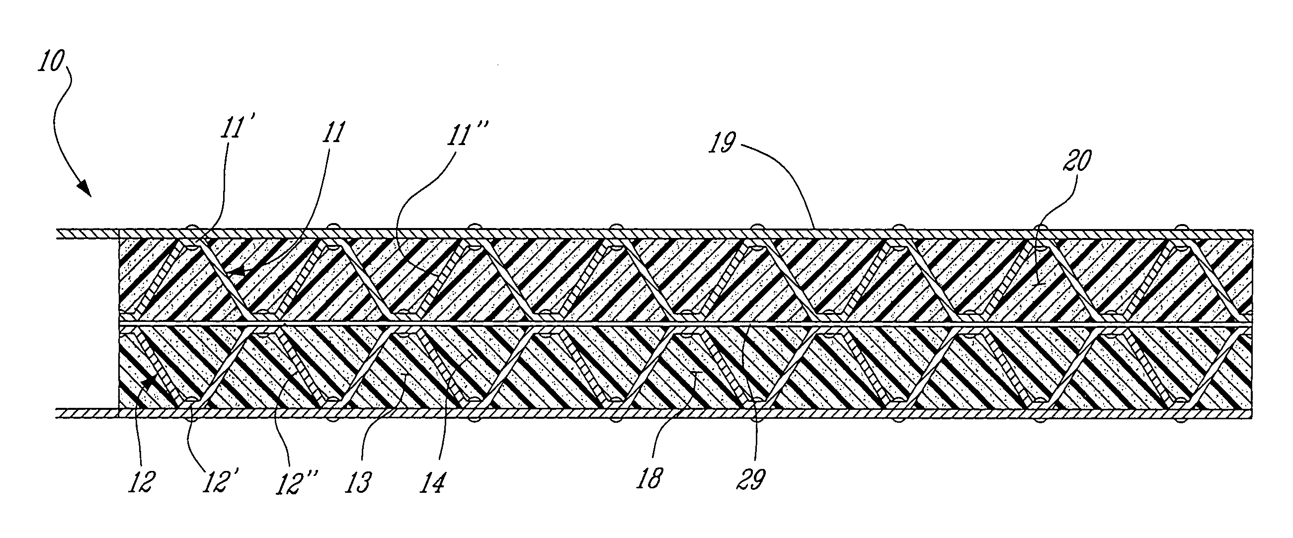
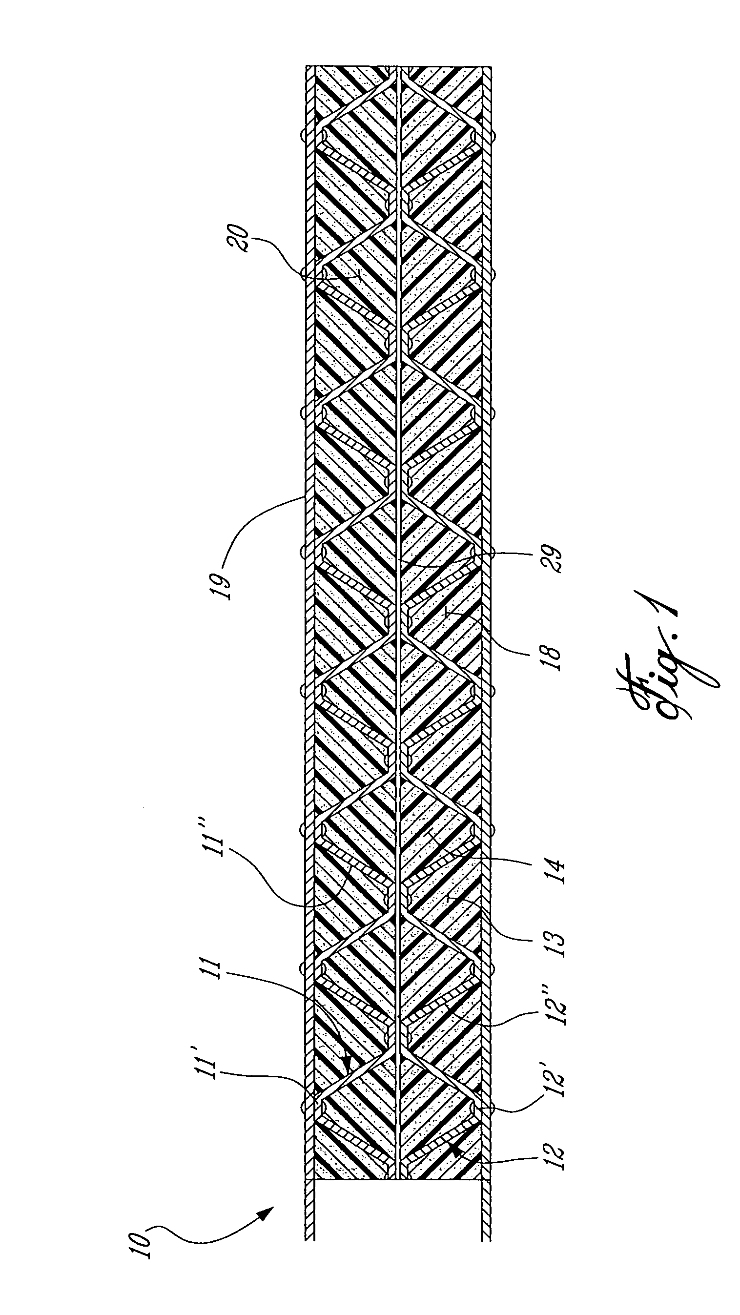
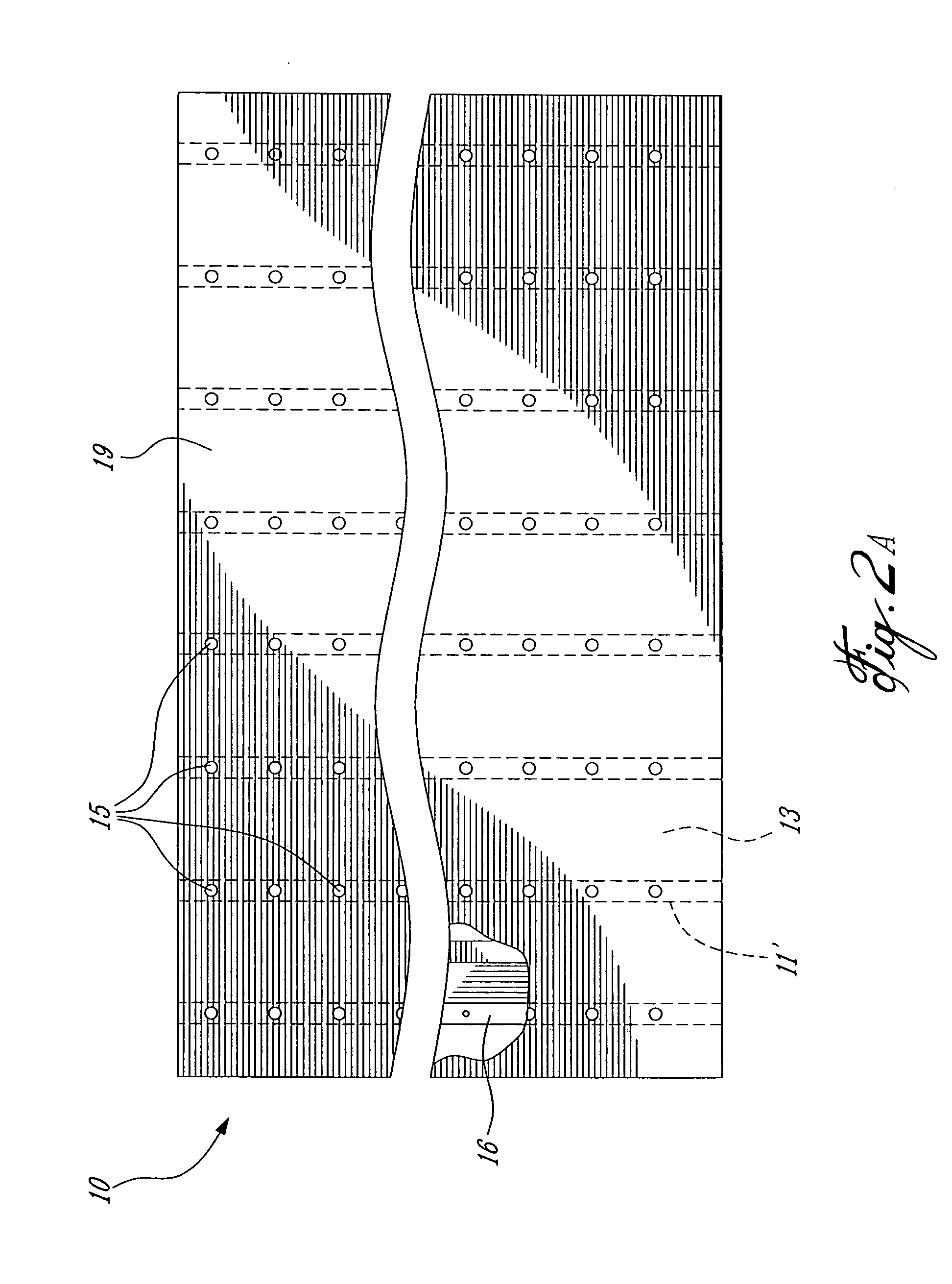
[0024]Referring now to the drawings and more particularly to FIGS. 1 and 2, there is shown generally at 10 a fiber reinforced thermoplastic composite panel constructed in accordance with one embodiment of the present invention. The panel comprises two corrugated sheets 11 and 12 formed of commingled glass fiber reinforced polypropylene (FRP) by a continuous roll forming process. Each of the corrugated sheets 11 and 12 define a plurality of opposed and offset spaced-apart connecting ridge sections 11′, 11″ and 12′ and 12″ and integrally formed intermediate trough sections 13 and 14 formed between the connecting ridge sections. The two corrugated sheets 11 and 12 are interconnected in superimposition, as hereinshown, by connection means which is hereinshown by high tensile bolts 15 interconnecting abutting ridge sections together. A web of FRP material having a thickness of about 1.6 mm is shown at 29 and interconnected by the bolts 15 between the connecting ridges between opposed dro...


PUM

PropertyMeasurementUnit
Thicknessaaaaaaaaaa
Thicknessaaaaaaaaaa
Thicknessaaaaaaaaaa

Abstract

A fiber reinforced thermoplastic composite panel is described. One use of the panel is to construct bridge decks although the panel may have several other uses. It comprises two flat plates formed of commingled glass fiber reinforced polypropylene secured in spaced parallel relationship to a core. The core is formed by either two corrugated sheets interconnected together along connecting ridge sections or else by a plurality of elongated FRP channel members disposed transversely between the flat plates. The corrugated sheets or channel members form hollow core spaces between the two flat plates and the core material and these hollow spaces are filled with a filler material to add stability to the panel. Both the flat plates and the core material are formed of commingled glass fiber reinforced polypropylene (FRP).

Description

TECHNICAL FIELD[0001]The present invention relates to a fiber reinforced thermoplastic composite panel for use in the construction of bridge decks, as an example, and wherein the components of the panel are fabricated from commingled glass fiber reinforced polypropylene material.[0002]The composite panel of the present invention was developed to replace current timber decks which are used in the construction of short span bridges and which could be more durable with an estimated service life of at least 75 years and which has less weight per surface area than these timber slabs making it much easier to install and replace if necessary while providing an excellent fatigue resistance.BACKGROUND ART[0003]Timber slabs conventionally used in these bridges are made of standard E-P-S logs 9197×203×4268 mm W×H×L). The logs are typically arranged in a staggered formation every 406 mm (clear spacing of 209 mm). A wearing surface made of the same wood is furnished atop of the cross log strips ...

Claims


Application Information

Patent Timeline
IPC IPC(8): E01D19/12
CPCB32B3/26B32B5/02E01D2101/40B32B27/32E01D19/125B32B17/04
Inventor BORAZGHI, HOSSEIN
Owner BORAZGHI HOSSEIN
Learn More