Floor beam assembly, system, and associated method

a technology of floor beams and assemblies, applied in the field of floor beams, can solve the problems of misalignment and installation time, and achieve the effect of reducing the incidence of misalignment and installation time, and quickly securing to the aircraft structur

Active Publication Date: 2008-04-03
THE BOEING CO
View PDF44 Cites 30 Cited by
  • Summary
  • Abstract
  • Description
  • Claims
  • Application Information

AI Technical Summary

Benefits of technology

[0007]Embodiments of the invention may address at least some of the above needs and achieve other advantages by providing an assembly, a system, and a method for installing floor beams within a structure. Generally, embodiments of the present invention include floor beams supported by brackets secured to a structure, such as an aircraft structure. Pads that are coupled to the aircraft structu

Problems solved by technology

Fasteners need not necessarily be used to attach the pads to the floor beam

Method used


Image

  • Floor beam assembly, system, and associated method
  • Floor beam assembly, system, and associated method
  • Floor beam assembly, system, and associated method

Examples


Embodiment Construction

[0019]The present invention now will be described more fully hereinafter with reference to the accompanying drawings, in which some, but not all embodiments of the invention are shown. Indeed, the invention may be embodied in many different forms and should not be construed as limited to the embodiments set forth herein; rather, these embodiments are provided so that this disclosure will satisfy applicable legal requirements. Like numbers refer to like elements throughout.

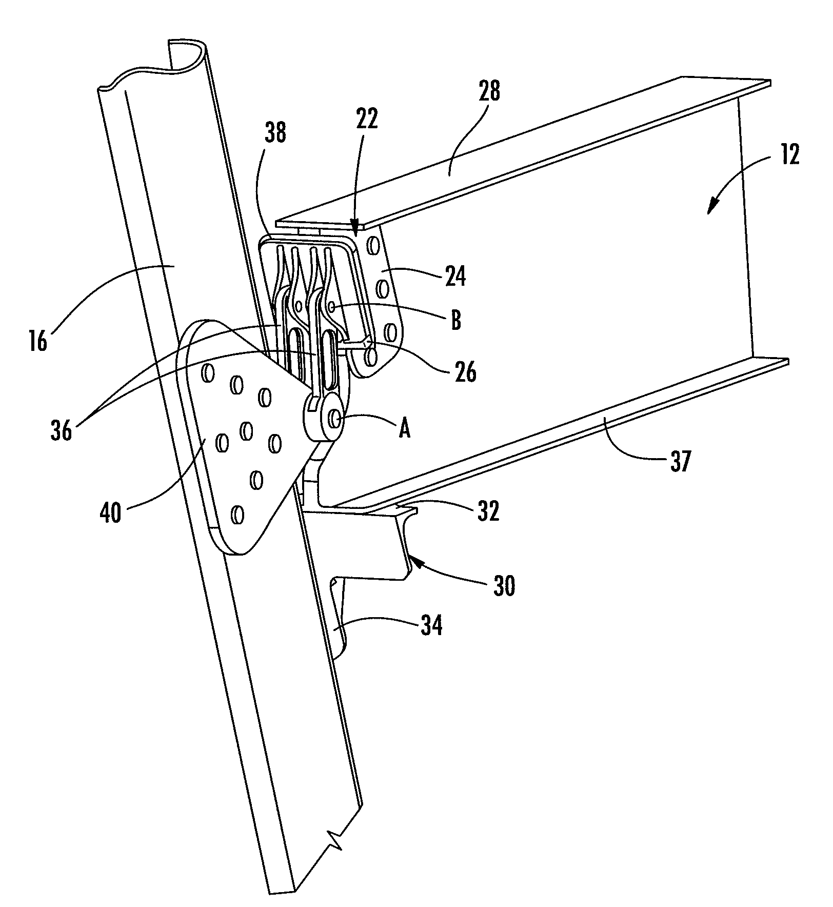
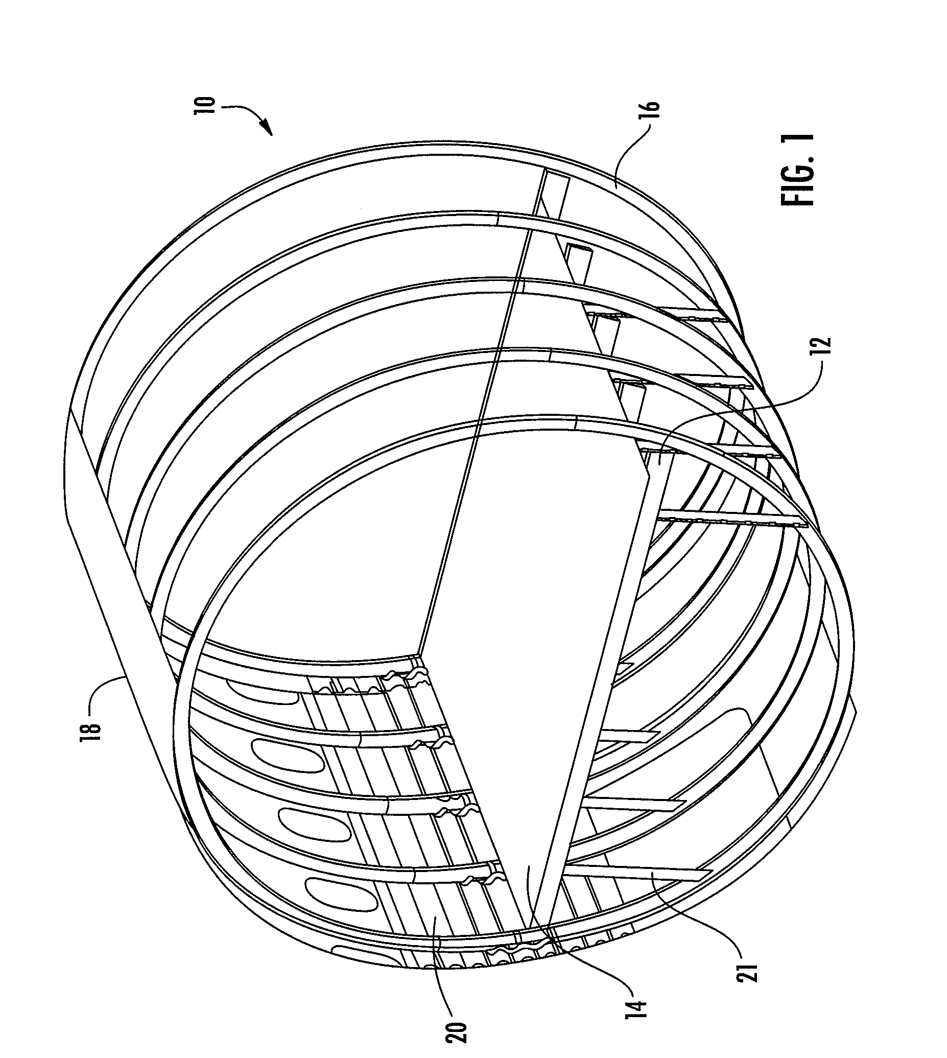
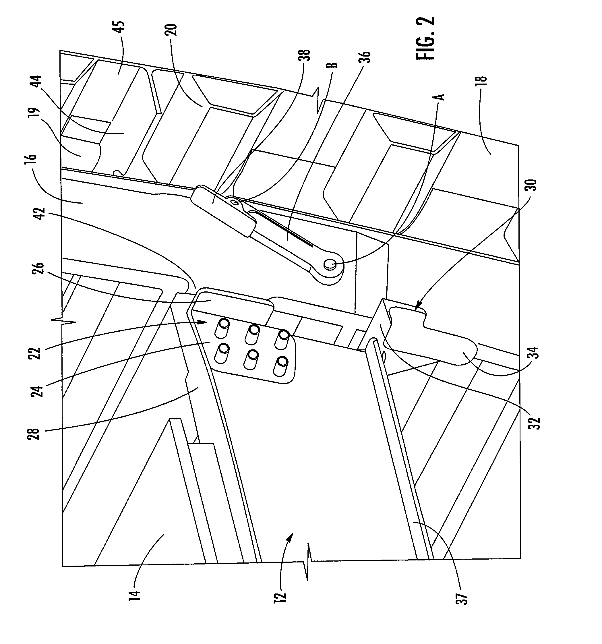
[0020]Referring now to the drawings and, in particular to FIG. 1, there is shown a system 10 for installing a floor beam assembly within an aircraft structure. In particular, the floor beam assembly includes a plurality of floor beams 12 and a floor panel 14 that is attached to a structure, such as a plurality of hoop frames 16. The floor beams 12 and floor panel 14 may be preassembled and secured to the hoop frames 16, as will be explained in further detail below. Although the system 10 is discussed in conjunction...


PUM


Abstract

A floor beam assembly, system, and method for installing floor beams within a structure are provided. According to one embodiment, a floor beam assembly for installing a floor beam within a structure is provided. The assembly includes at least one floor beam and at least one floor beam bracket attached to a respective floor beam. The assembly also includes at least one pivot arm pivotally attached to the structure. In addition, the assembly includes a pad attached to the at least one pivot arm, wherein the at least one pivot arm is configured to pivot the pad to a position proximate to a respective floor beam bracket to be attached thereto.

Description

BACKGROUND OF THE INVENTION[0001]1) Field of the Invention[0002]Embodiments of the present invention relate to floor beams and, more particularly, to apparatus, systems, and methods for installing floor beams within a structure.[0003]2) Description of Related Art[0004]The floor of an aircraft is typically built up from a series of spaced apart transverse floor beams that span across oval hoop frames to form the structural framework for the aircraft fuselage. The floor beams are usually aluminum and are individually attached with fasteners at each end to the hoop frames via a lap joint. The joint formed between the floor beam and the hoop frame bears the transverse and shear loads applied to the floor beam. Loads applied in the fore and aft direction are bore by longitudinal shear trusses between the floor and the fuselage floor.[0005]Current techniques for joining the floor beams and hoop frames require precise installation of mate-drilled holes between the floor beams and the hoop ...

Claims


Application Information

Patent Timeline
IPC IPC(8): E04G21/14
CPCB64C1/18B64C1/068
Inventor WOOD, JEFFREY H.FOGARTY, JOHN H.
Owner THE BOEING CO
Why Eureka
Try Eureka