Heat dissipating system and method

Inactive Publication Date: 2008-04-03
LUO CHIN KUANG
View PDF2 Cites 38 Cited by
  • Summary
  • Abstract
  • Description
  • Claims
  • Application Information

AI Technical Summary

Benefits of technology

[0009]Therefore, the object of the present invention is to provide a heat dissipating system that can reduce noise to a minimum and that can effectively enhance heat dissipation. The present invention also provides a method for dissipating heat from a heat source. According to one aspect of this invention, a heat dissipating system comprises: a heat-absorbing unit having at least one cavity body adapted to contact a heat source, and a working

Problems solved by technology

1. Since the aforementioned liquid-cooling heat dissipating system relies on the pressure-increasing pump 13 to circulate the working fluid, the system not only has more components, is more costly, and is more noisy, but also generates more heat itself due to the pressure-increasing pump 13. This runs counter to efforts at reducing the temperature of the working fluid in the syste

Method used


Image

  • Heat dissipating system and method
  • Heat dissipating system and method
  • Heat dissipating system and method

Examples


Embodiment Construction

[0020]Before the present invention is described in greater detail, it should be noted that the same reference numerals have been used to denote like elements throughout the specification.

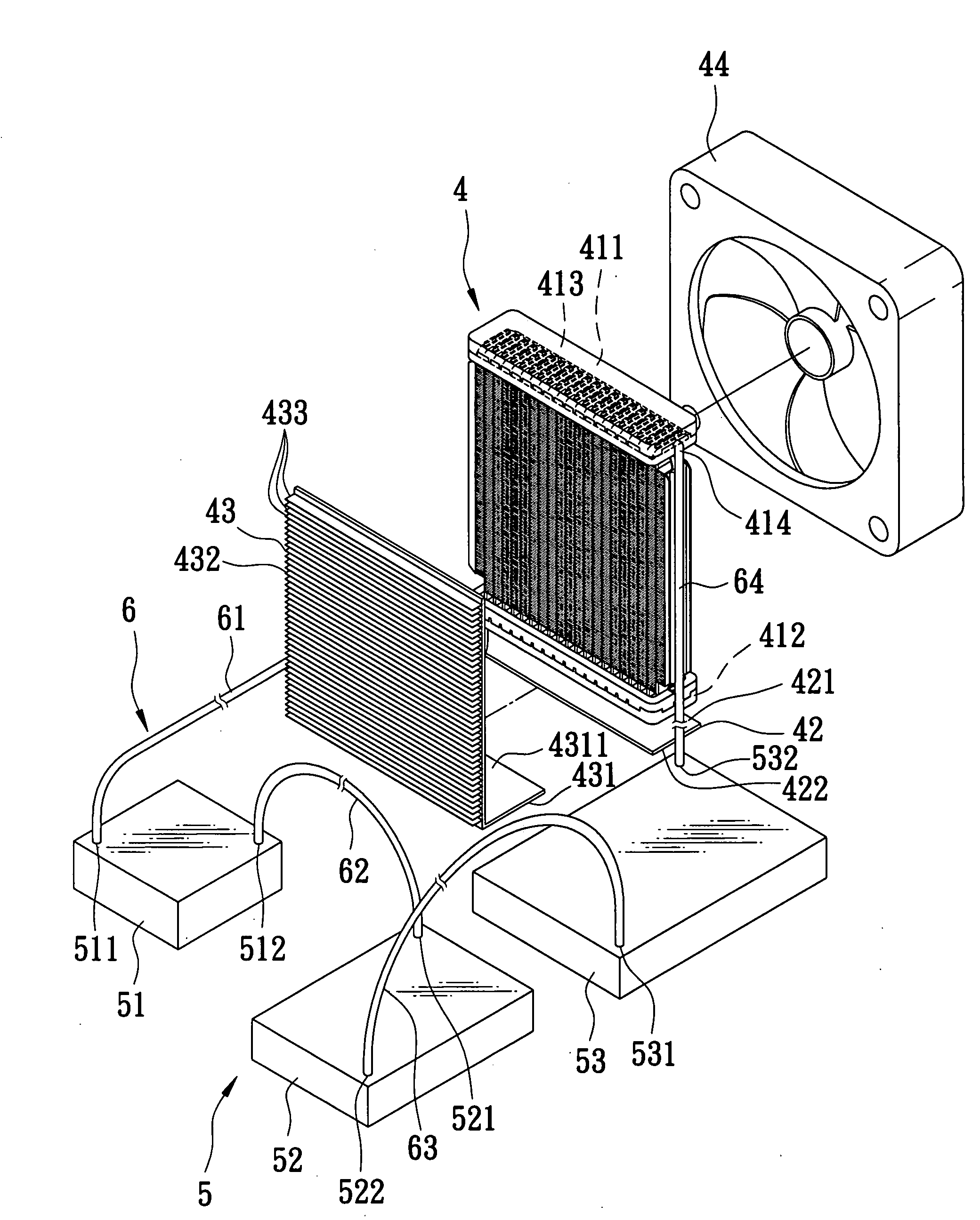
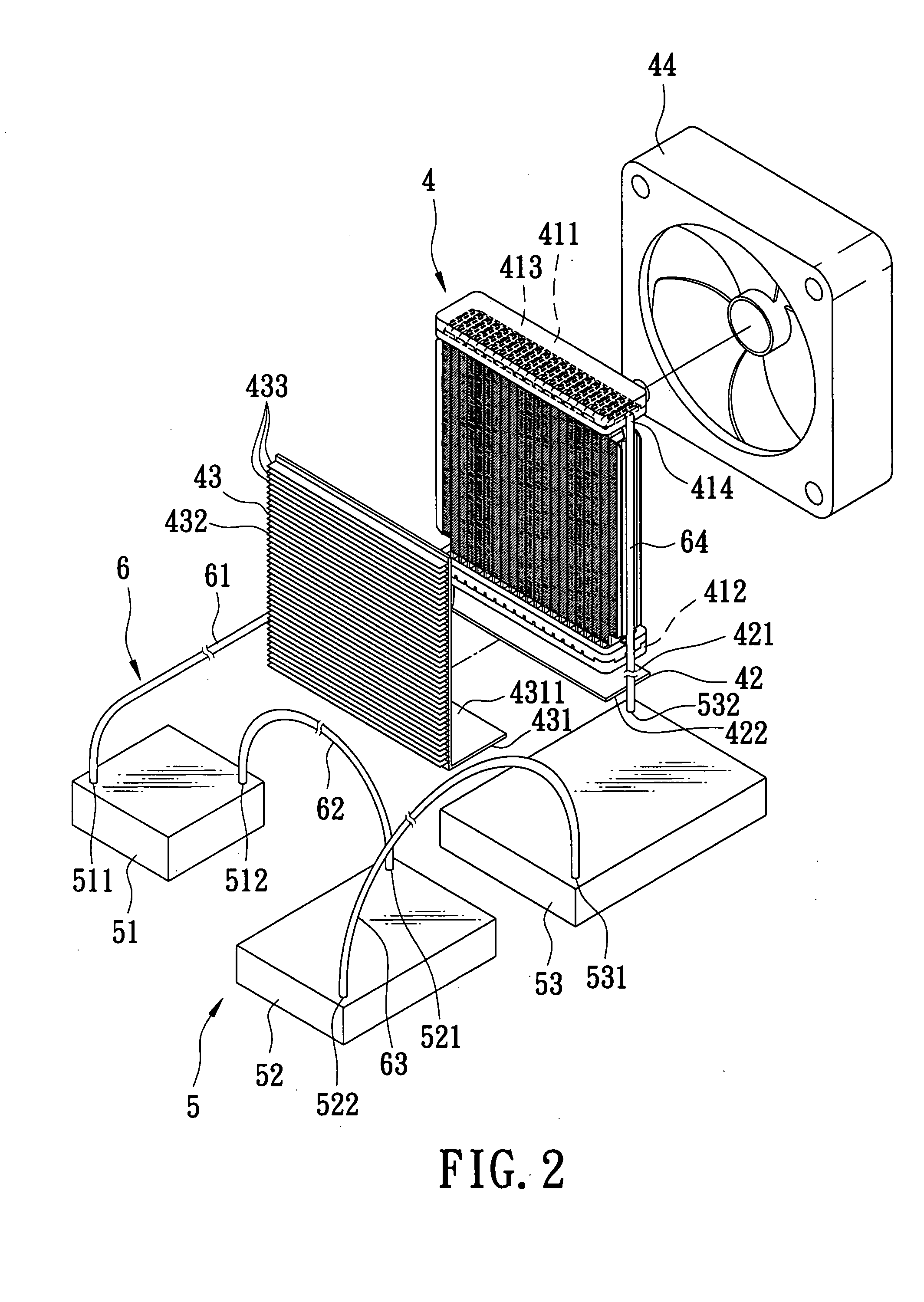
[0021]Referring to FIGS. 2 to 5, the first preferred embodiment of a heat dissipating system according to the present invention is installed in a computer module 3. The computer module 3 has a housing 33 defining upper and lower chambers 31, 32, a mounting board 34 fixed inside the lower chamber 32, and a plurality of module chips 35 mounted on the mounting board 34. The heat dissipating system of the present invention comprises a condenser 4, a heat-absorbing unit 5, and a tubing unit 6. The module chips 35 are heat sources to undergo heat dissipation by the system of the present invention. The condenser 4 is disposed in the upper chamber 31 of the computer module 3, and includes a vapor-receiving part 411 formed on a top end thereof, an inlet 414 connected fluidly to the vapor-receiving part 411, ...


PUM


Abstract

A heat dissipating system includes: a heat-absorbing unit having at least one cavity body adapted to contact a heat source, and a working fluid received in the cavity body; a condenser to condense the working fluid; and a tubing unit connected fluidly to the condenser and the heat-absorbing unit. The working fluid flows through the tubing unit to circulate from the condenser to the heat-absorbing unit by gravity and from the heat-absorbing unit to the condenser by natural convection. The tubing unit forms a closed circulating loop with the heat-absorbing unit and the condenser.

Description

CROSS-REFERENCE TO RELATED APPLICATION[0001]This application claims priority of Taiwanese Application No. 095136005, filed on Sep. 28, 2006.BACKGROUND OF THE INVENTION[0002]1. Field of the Invention[0003]The invention relates to heat dissipation, more particularly to a heat dissipating system and method.[0004]2. Description of the Related Art[0005]Referring to FIG. 1, a liquid-cooling heat dissipating system, as disclosed in Taiwanese Publication No. M295424, includes a heat sink 11 for exchanging heat with external cold air by convection, a thermoelectric cooler 12, a pressure-increasing pump 13 to circulate a working fluid within the system, a liquid-cooling connector 14 in contact with a heat source 2, three input pipes 15 for interconnecting the heat sink 11, the thermoelectric cooler 12, the pump 13, and the liquid-cooling connector 14 in series, an output pipe 16 connected fluidly to the heat sink 11 and the liquid-cooling connector 14, and a fan 17 for directing a current of ...

Claims


Application Information

Patent Timeline
IPC IPC(8): F25B15/00
CPCF25B21/02H01L23/427H01L35/30H01L2924/0002H01L2924/00H10N10/13G06F1/20
Inventor LUO, CHIN-KUANG
Owner LUO CHIN KUANG
Why Eureka
Try Eureka