Screen Synchronous Control Apparatus

Active Publication Date: 2008-04-03
MITSUBISHI ELECTRIC CORP
View PDF4 Cites 16 Cited by
  • Summary
  • Abstract
  • Description
  • Claims
  • Application Information

AI Technical Summary

Benefits of technology

[0007]Therefore, the present invention provides an advantage of being able to simultaneously display the same description on the plurality of display screens with the simple structure.

Problems solved by technology

A problem with prior art multi screen synchronization systems is that because most of them are so constructed as to achieve time synchronization among two or more control apparatus, to issue a time stamp to a drawing instruction, or to achieve synchronization among two or more control apparatus in terms of signal processing using a mechanism for achieving synchronization between them, such as GenLock, the structure of the whole system becomes complicated.
However, patent reference 1 simply relates to a technology for transmitting a timing signal to other adjacent control apparatus in order to secure the continuity of display elements, but does not disclose any technology for simultaneously generating screen displays.

Method used


Image

  • Screen Synchronous Control Apparatus
  • Screen Synchronous Control Apparatus
  • Screen Synchronous Control Apparatus

Examples


embodiment 1

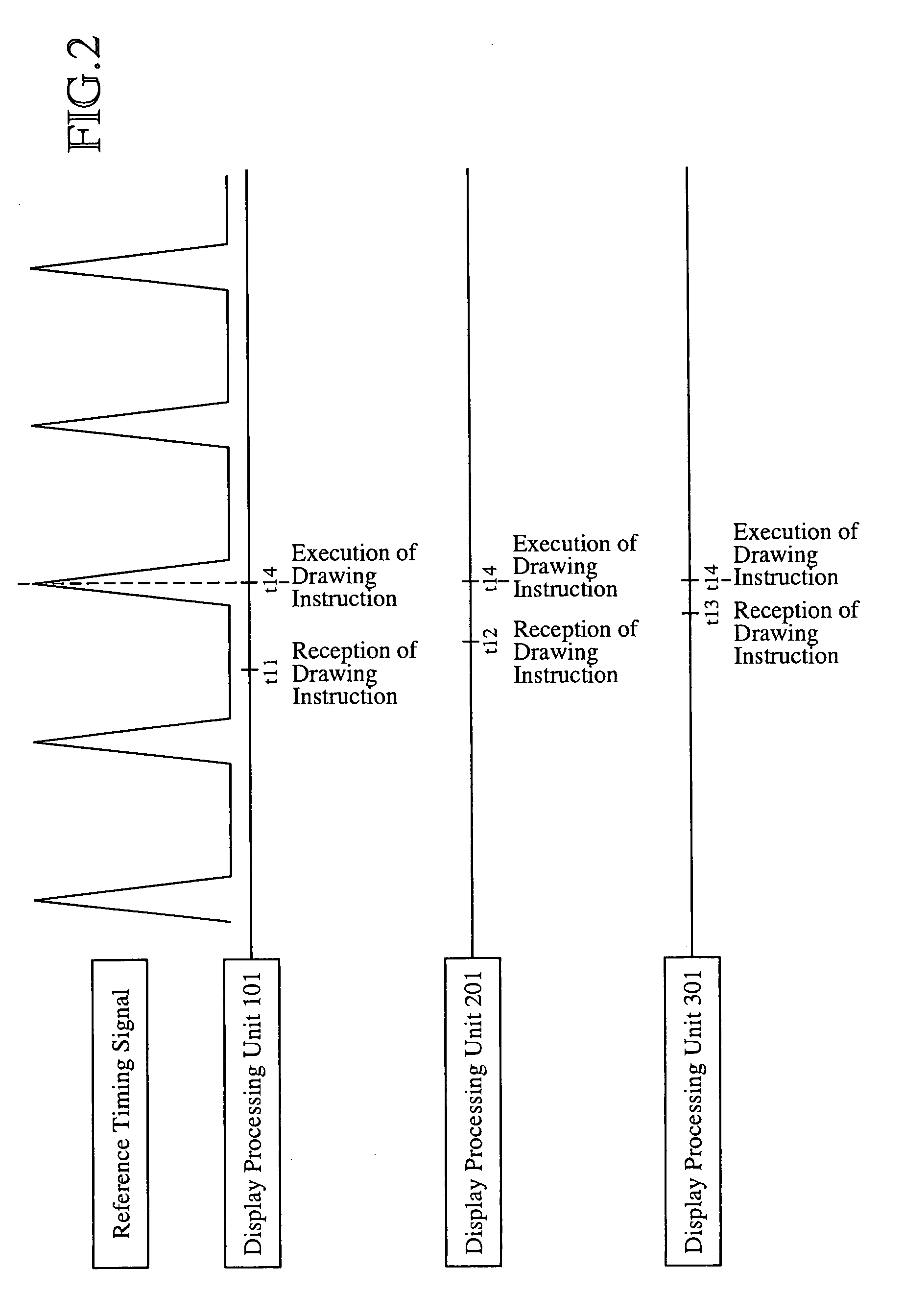
[0017]In this embodiment 1, a synchronous control method of issuing only a reference timing signal at regular intervals via broadcast communications, transmitting drawing instructions one after another, and simultaneously displaying data at a timing determined by the reference timing signal by means of two or more receive sides will be explained.

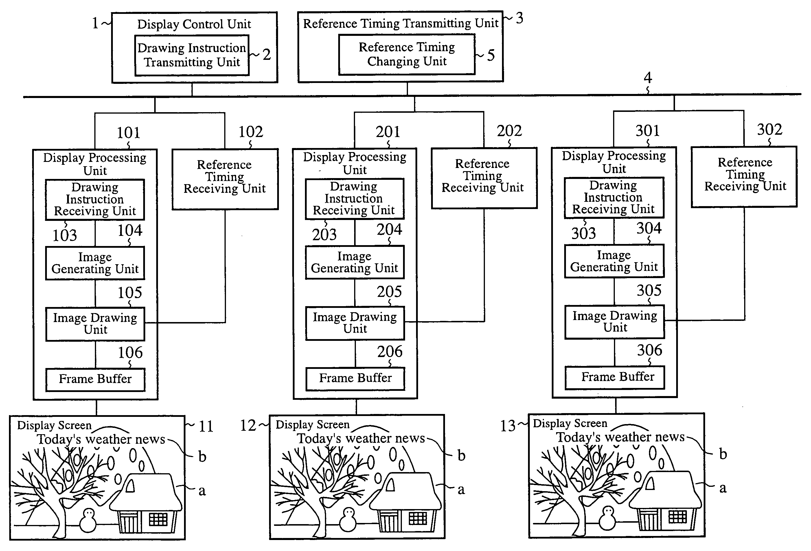
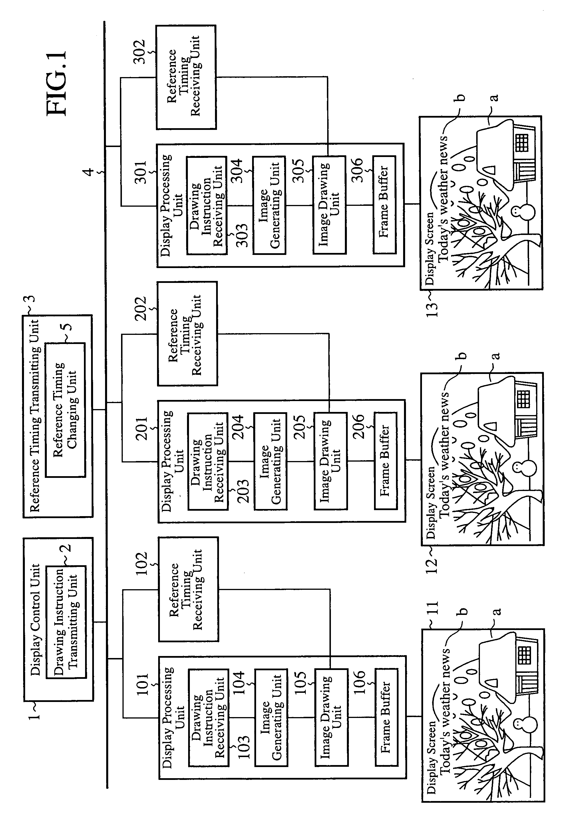
[0018]FIG. 1 is a block diagram showing the structure of a screen synchronous control apparatus in accordance with embodiment 1 of the present invention. This screen synchronous control apparatus is provided with a display control unit 1, a reference timing transmitting unit 3, a plurality of display processing units 101, 201, and 301 which correspond to a plurality of display screens 11, 12, and 13, respectively, and a plurality of reference timing receiving units 102, 202, and 302. The display control unit 1, reference timing transmitting unit 3, and display processing units 101, 201, and 301 are connected to one another via a communicatio...

embodiment 2

[0031]In this embodiment 2, a synchronous control method of issuing a reference timing signal and a drawing instruction at regular intervals via broadcast communications, and simultaneously displaying data at a timing determined by the reference timing signal at a plurality of receive sides will be explained.

[0032]FIG. 3 is a block diagram showing the structure of a screen synchronous control apparatus in accordance with embodiment 2 of the present invention. This screen synchronous control apparatus is provided with a display control unit 1, a reference timing transmitting unit 3, and a plurality of display processing units 101 and 201 which correspond to the plurality of display screens 11 and 12, respectively. The display control unit 1, reference timing transmitting unit 3, and display processing units 101 and 201 are connected to one another via a communication line 4. These display processing units 101 and 201 are placed at, for example, a plurality of places, such as station ...

embodiment 3

[0047]In this embodiment 3, a synchronous control method of issuing a reference timing signal at regular intervals via broadcast communications, transmitting drawing instructions one after another, and simultaneously displaying an image at a plurality of display sides by simultaneously carrying out a switching between frame buffers for display at a timing determined by the reference timing signal will be explained.

[0048]FIG. 5 is a block diagram showing the structure of a screen synchronous control apparatus in accordance with embodiment 3 of the present invention. This screen synchronous control apparatus is provided with a display control unit 1, a reference timing transmitting unit 3, a plurality of display processing units 101 and 201 which correspond to a plurality of display screens 11 and 12, respectively, and a reference timing receiving unit 102. The display control unit 1, reference timing transmitting unit 3, display processing units 101 and 201, and reference timing rece...


PUM


Abstract

A screen synchronous control apparatus includes a reference timing transmitting unit 3 for transmitting a reference timing signal about display of a plurality of display screens 11, 12, and 13 at predetermined intervals, a display control unit 1 for transmitting a drawing instruction for displaying display data on the plurality of display screens 11, 12, and 13, and a plurality of display processing units 101, 201, and 301 each for receiving the drawing instruction transmitted from the display control unit 1, for executing the drawing instruction according to the reference timing signal transmitted from the reference timing transmitting unit 3, and for displaying the display data on the corresponding one of the display screens 11, 12, or 13.

Description

FIELD OF THE INVENTION[0001]The present invention relates to a screen synchronous control apparatus for simultaneously displaying data in a plurality of display screens. Background of the Invention[0002]A problem with prior art multi screen synchronization systems is that because most of them are so constructed as to achieve time synchronization among two or more control apparatus, to issue a time stamp to a drawing instruction, or to achieve synchronization among two or more control apparatus in terms of signal processing using a mechanism for achieving synchronization between them, such as GenLock, the structure of the whole system becomes complicated.[0003]Patent reference 1 discloses a system in which each of two or more control apparatus which are disposed for two or more display screens outputs a screen-display signal on the basis of inputted display information, when processing display elements relevant to two or more screens adjacent to the screen thereof, transmits a timing...

Claims


Application Information

Patent Timeline
IPC IPC(8): G09G5/00
CPCG06F3/1446G09G2300/026G09G5/12G06F3/1454
Inventor NAITO, MANAMITANAKA, ATSUSHIHAGIWARA, TOSHIYUKITSUBAKI, YASUNORI
Owner MITSUBISHI ELECTRIC CORP
Why Eureka
Try Eureka