Image processing method and apparatus, and image forming method and apparatus

Inactive Publication Date: 2008-04-03
FUJIFILM CORP
View PDF17 Cites 25 Cited by
  • Summary
  • Abstract
  • Description
  • Claims
  • Application Information

AI Technical Summary

Benefits of technology

[0034]According to the present invention, since the pixel positions in boundary regions of dot patterns, where the banding correction performance is liable to decline when performing a dens

Problems solved by technology

However, in the method disclosed in Japanese Patent Application Publication No. 2004-142196, it is difficult to correct for the banding caused by recording errors other than ejection failure, in other words, it is difficult to correct for the banding caused by variation in the ejected volume of the ink droplet or the ejection direction.
Furthermore, the technology described in Japanese Patent Application Publication No. 2004-142196 does not include the concept of using the nozzles surrounding a nozzle suffering ejection failure in order to perform correction, and the corrective performance of this technology is low.
Although the technologies described in Japanese Patent Application Publication No. 2001-0

Method used


Image

  • Image processing method and apparatus, and image forming method and apparatus
  • Image processing method and apparatus, and image forming method and apparatus
  • Image processing method and apparatus, and image forming method and apparatus

Examples


first embodiment

of the Present Invention

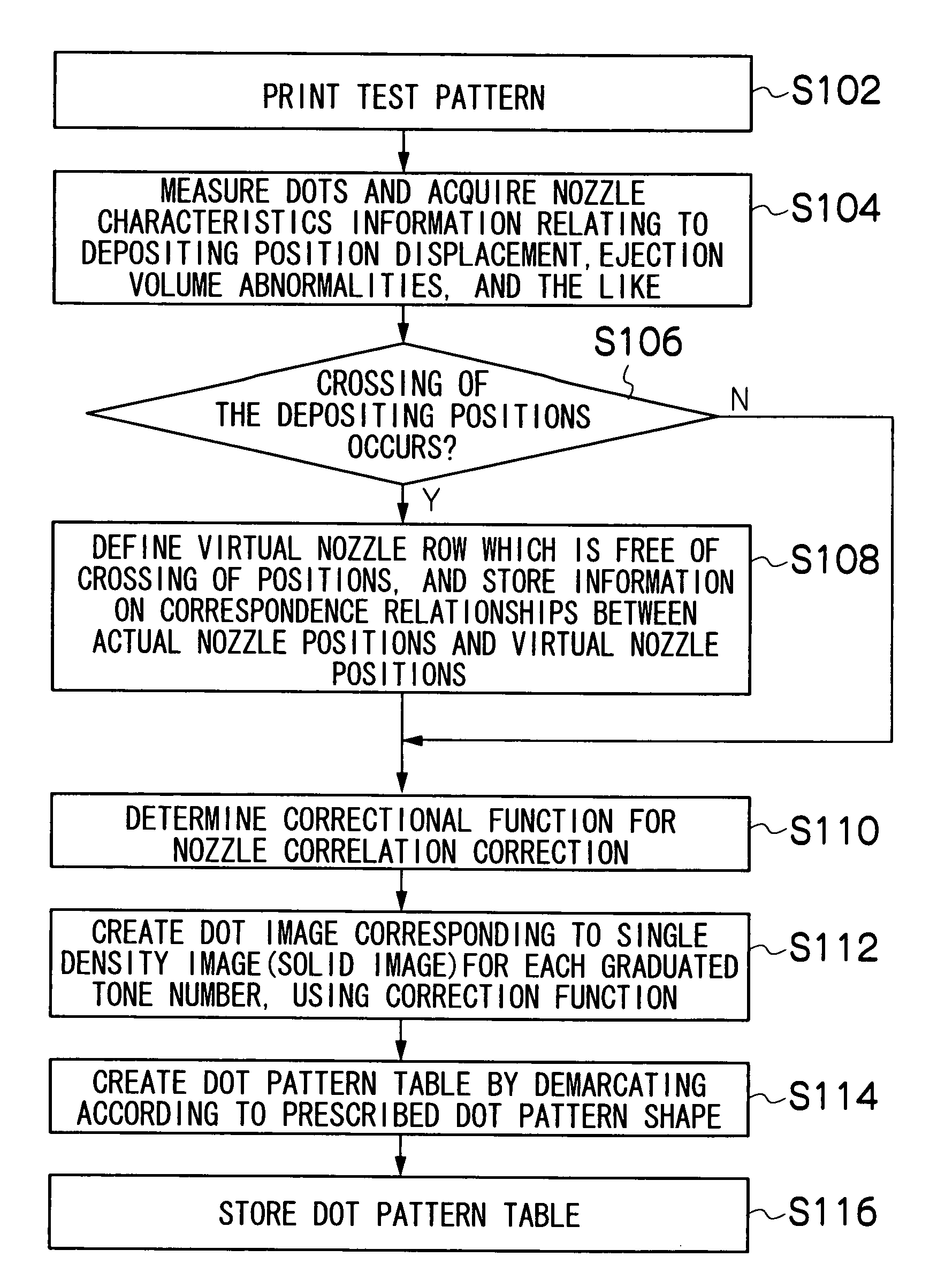
[0084]An image processing method according to an embodiment of the present invention is described below. The image processing method according to the present embodiment uses, in principle, an image processing technique which combines the multiple-value error diffusion processing and density pattern processing described above. In the present embodiment, the shape of the dot pattern in the dot pattern table is different from that of the method used in the related art. In other words, in the dot pattern table used in the related art, as described above with reference to FIG. 3, the dot pattern shape is specified as a rectangular block of (k×1) pixels, composed of k pixels in the main scanning direction (alignment direction of the nozzle row, also refereed to as “first direction”, the vertical direction in FIG. 3), and 1 pixels in the sub-scanning direction. In the dot pattern table used in the related art, the dot patterns are arranged linearly in the vertical a...

second embodiment

of the Present Invention

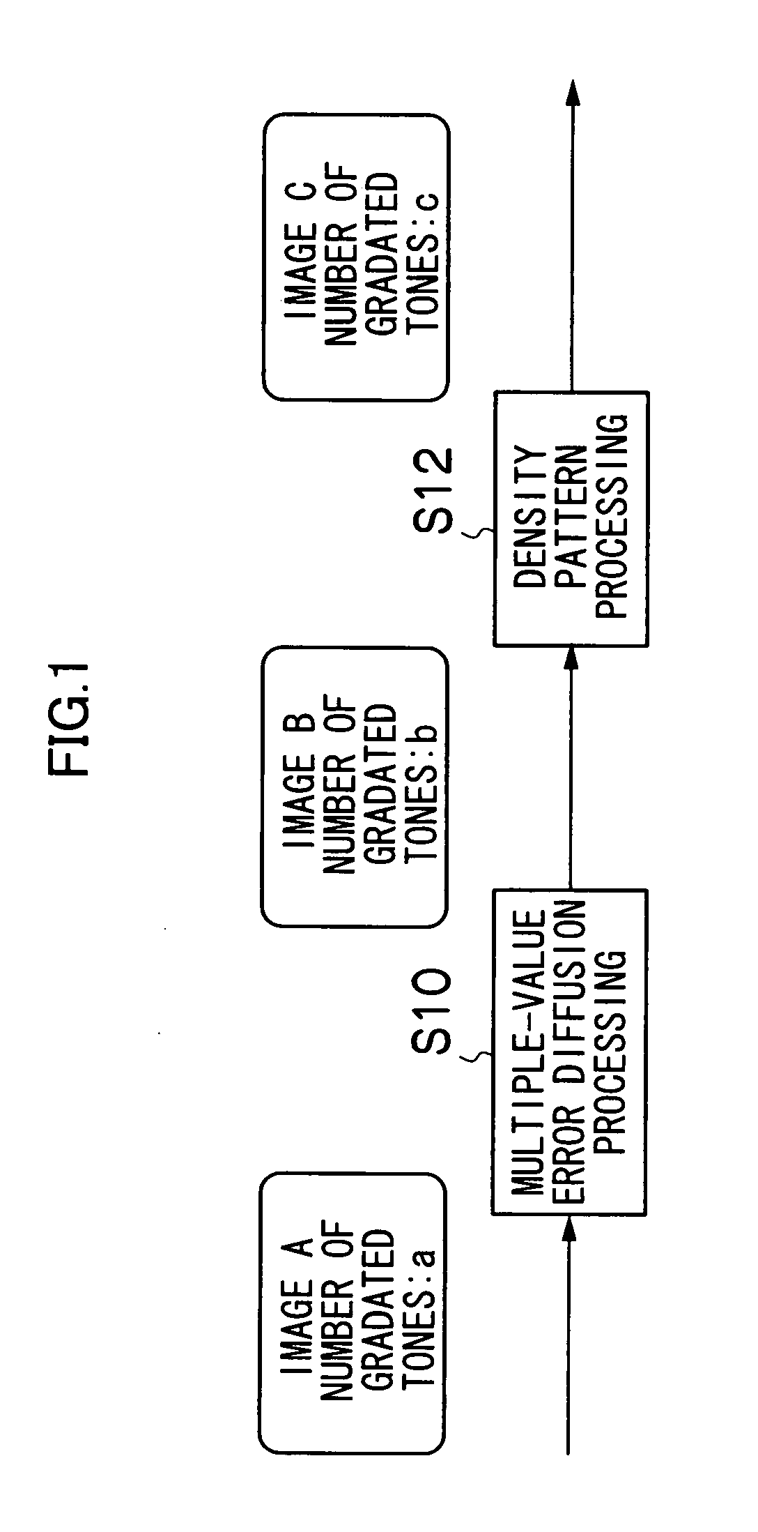
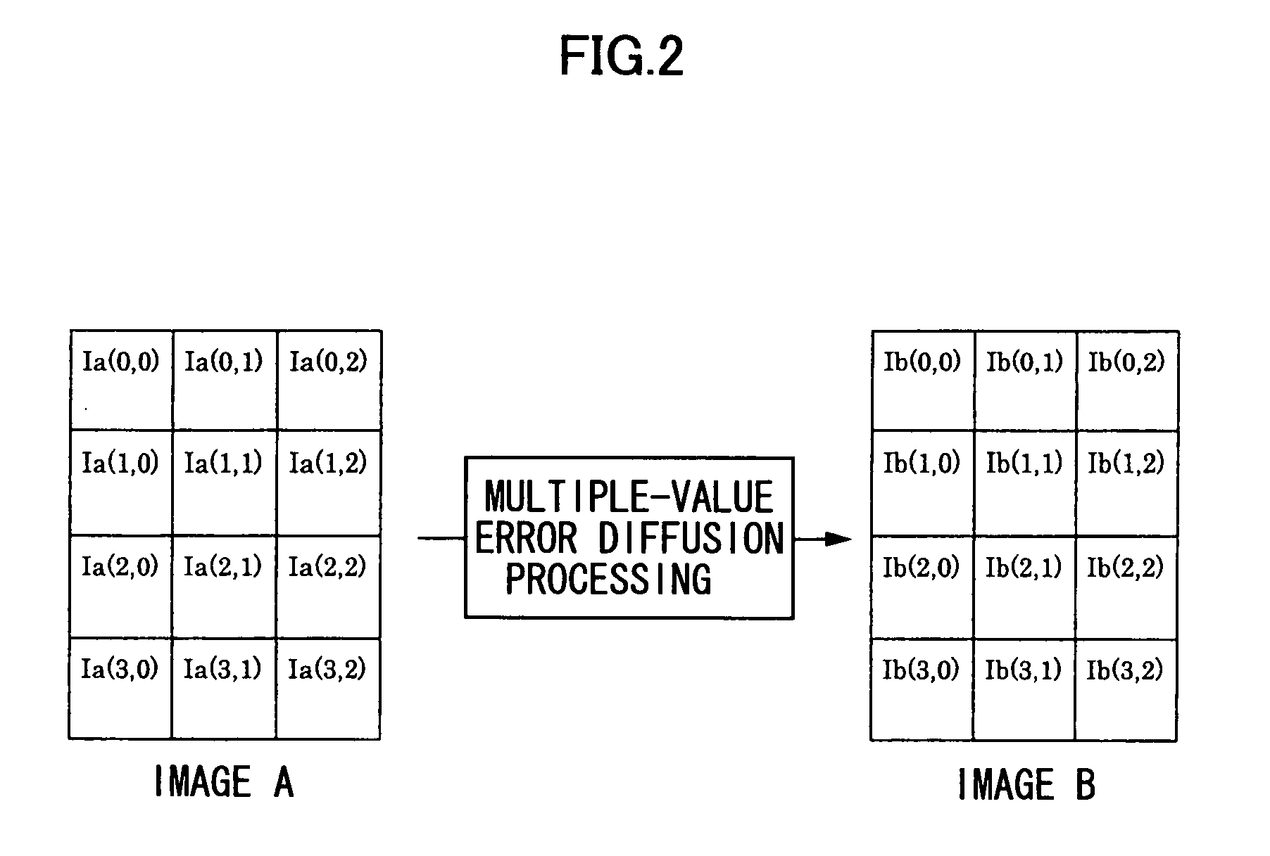
[0093]An image processing method according to a second embodiment of the present invention is described below. FIG. 8 is a conceptual diagram of multiple-value error diffusion processing used in the second embodiment. In the present embodiment, instead of the “multiple-value error diffusion process” described in FIG. 1, a “pixel shift multiple-value error diffusion process (also referred to as “pixel offset multiple-value error diffusion process”)” as shown in FIG. 8 is carried out.

[0094]The image B (number of graduated tones: b) obtained by the pixel offset multiple-value error diffusion process described here is an image having a pixel arrangement in which the pixel positions in a row of pixels aligned in the main scanning direction (a main scanning direction pixel row) are offset (shifted) by a distance corresponding to half a pixel in the main scanning direction, with respect to a pixel row that is adjacent to that row in terms of the sub-scanning directi...

third embodiment

[0107]The image processing method according to a third embodiment of the present invention is described below. FIG. 11 is a diagram showing a dot pattern table used in the third embodiment. In the third embodiment, instead of the dot pattern table shown in FIG. 10, the dot pattern table shown in FIG. 11 which is defined on the basis of cross-shaped dot patterns 50 is used. The case of the dot pattern table shown in FIG. 11 is similar to the embodiments described above with reference to FIG. 7 or FIG. 10, with the exception of the fact that, in the address calculation for specifying the dot pattern at the position corresponding to the position (x,y) of the pixel, special conditions corresponding to the end section shapes are added, (more specifically, if mod(y / (N / n)) is zero or a final value, which respectively corresponds to a dot pattern block row in the main scanning direction that is located at the far left in FIG. 11, and a dot pattern block row in the main scanning direction th...


PUM


Abstract

An image processing method coverts multiple-value image data of an image into a plurality of dot patterns to form the image on a recording medium, the multiple-value image data being constituted of a plurality of pixels each of which has a graduated tone value that is one of graduated tone numbers, the image being formed by means of: a recording head which has a plurality of recording elements arranged in a first direction, the recording elements forming dots on the recording medium to form the image in accordance with the dot patterns, each of the dot patterns representing an arrangement of the dots corresponding to the graduated tone value for each of the pixels; and a relative movement device which causes the recording head and the recording medium to move relative to each other in a second direction that is substantially perpendicular to the first direction. The image processing method includes the steps of: preparing a plurality of dot pattern tables respectively for the graduated tone numbers, each of the dot pattern tables being demarcated into blocks of the dot patterns correlated with positions of the pixels so that a block row constituted of two of the blocks of the dot patterns that are mutually adjacent in the second direction is defined by a boundary in the second direction that does not coincide with a straight line parallel to the second direction, the dot patterns in each of the dot pattern tables being determined so that banding caused by recording characteristics of the recording elements is corrected in accordance with a correlation between each of the recording elements and surrounding recording elements of said each of the recording elements; and then selecting the dot patterns respectively for the pixels from the dot pattern tables in accordance with the positions of the pixels and the graduated tone values of the pixels to convert the multiple-value image data into the dot patterns.

Description

BACKGROUND OF THE INVENTION[0001]1. Field of the Invention[0002]The present invention relates to an image processing method and apparatus and to an image forming method and apparatus, and more particularly, to half-toning technology used in an image forming apparatus of a dot recording system, which is typified by an inkjet printer.[0003]2. Description of the Related Art[0004]An image forming apparatus has been known which forms an image on a recording medium by means of dots, such as an inkjet printer, a thermal printer, and an LED printer, and the like. In an image forming apparatus of this kind, an image is formed by means of a plurality of dots formed by liquid ink droplets, toner particles, or the like, and therefore, essentially, an image is reproduced by depositing or not depositing dots at locations on a recording medium, such as a white paper. Since the number of inks available is limited, a half-toning method has been known which is used to represent continuous tonal gradu...

Claims


Application Information

Patent Timeline
IPC IPC(8): B41J2/205G06K15/00
CPCB41J29/393H04N1/4055H04N1/4052G06K15/10
Inventor YAMAZAKI, YOSHIROU
Owner FUJIFILM CORP
Why Eureka
Try Eureka