

Battery pack and manufacturing method thereof
a technology of battery pack and manufacturing method, which is applied in the manufacture of final products, cell components, electrochemical generators, etc., can solve the problems of prone to damage of first battery b>10/b>a, harmful effect, and harm to the battery
- Summary
- Abstract
- Description
- Claims
- Application Information
AI Technical Summary
Benefits of technology
Problems solved by technology
Method used
Image

Examples
Embodiment Construction
)
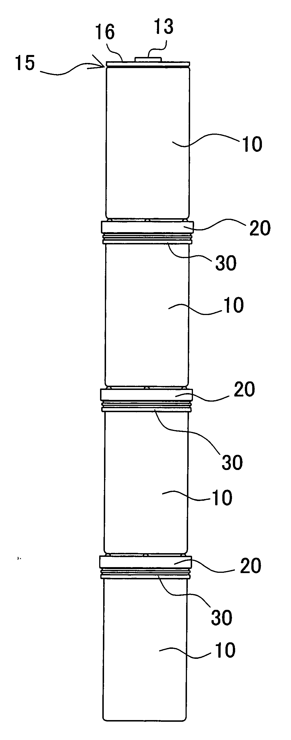
[0036]In the battery pack shown in FIG. 8, a plurality of rechargeable batteries 10 are connected in series and linearly coupled to each other. In the case of the battery pack thus structured, the plurality of batteries 10 are connected in series and are used mainly with an electric motor vehicle such as a hybrid vehicle. It should be noted that that the inventive battery pack is also able to be used for such an application as may require a high power like in other than an electric motor vehicle. The illustrated battery pack is connected in series by linearly coupling the rechargeable batteries 10 which are tubular batteries. The battery pack is also able to be made up with polygonal secondary batteries being linearly coupled for connection in series.
[0037]A rechargeable battery to be used for a battery pack includes any rechargeable type of batteries including a nickel-hydrogen battery, a lithium-iron secondary battery, and a nickel-cadmium battery. Here, a nickel-hydrogen battery...
PUM
| Property | Measurement | Unit |
|---|---|---|
| current | aaaaa | aaaaa |
| current | aaaaa | aaaaa |
| inner diameter | aaaaa | aaaaa |
Abstract
Description
Claims
Application Information