Lead plate-attached coin-type battery whose lead plate is attached to exclusively either an outer can or a cap

a lead plate and battery technology, applied in the direction of cell components, flat cell grouping, sustainable manufacturing/processing, etc., can solve the problems of insufficient bonding strength between the lead plate and the conductive land on the circuit board, the mounting height of the coin-type battery, and the inability to meet the requirements of the battery. to achieve the effect of suppressing the outflow of solder

Inactive Publication Date: 2008-04-03
FDK CORP +1
View PDF1 Cites 6 Cited by
  • Summary
  • Abstract
  • Description
  • Claims
  • Application Information

AI Technical Summary

Benefits of technology

[0027] Also, in the lead plate-attached coin-type battery pertaining to the present invention, the one or more projections may have been formed so as to, in a planar view of the one of the outer can and the cap to which the lead plate is -not attached, be embankment-shaped having a portion missing and surround a formation area of the one or more projections. This enable...

Problems solved by technology

In the mounting method proposed in the aforementioned document, one of the lead plates is omitted when mounting the coin-type battery to the circuit board, thereby enabling reducing the mounted height of the coin-type-battery on the circuit board by the thickness of the omitted lead plate, which is not possible when lead plates are attached to both the outer can and the negative cap in mounting.
However, when using the mounting method proposed in the aforementioned document, there are cas...

Method used


Image

  • Lead plate-attached coin-type battery whose lead plate is attached to exclusively either an outer can or a cap
  • Lead plate-attached coin-type battery whose lead plate is attached to exclusively either an outer can or a cap
  • Lead plate-attached coin-type battery whose lead plate is attached to exclusively either an outer can or a cap

Examples


embodiment

[0037] 1. Structure of Lead Plate-Attached Coin-Type Battery 1

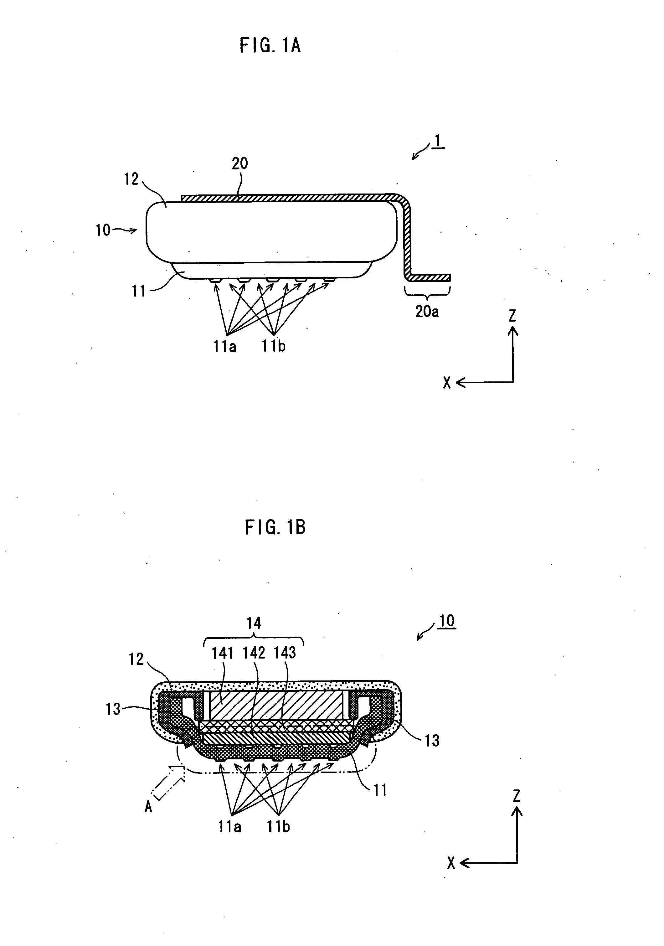
[0038] The following describes the structure of a lead plate-attached coin-type battery 1 pertaining to the present embodiment with reference to FIG. 1A.

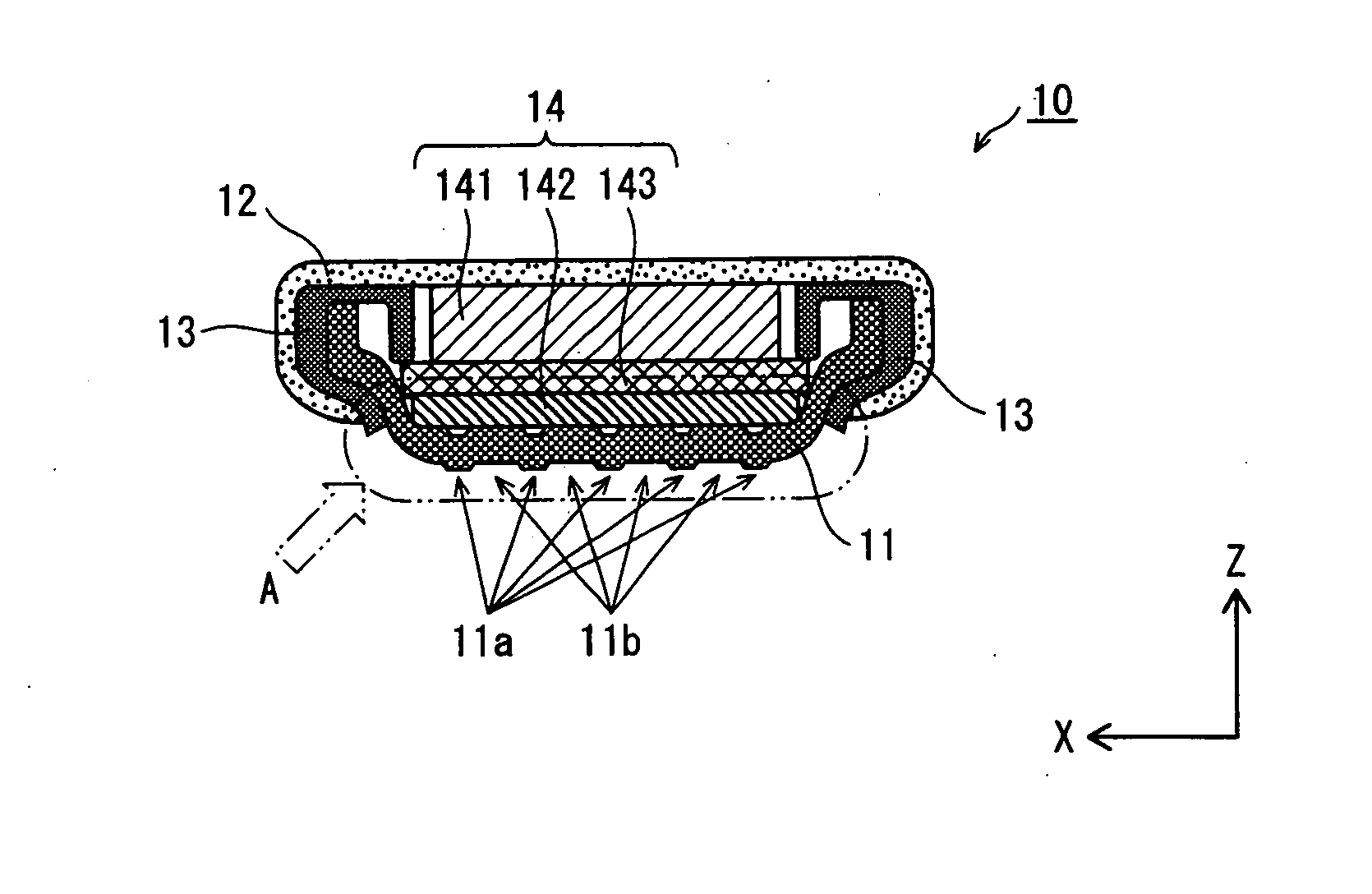
[0039] As shown in FIG. 1A, the lead plate-attached coin-type battery 1 pertaining to the present embodiment includes a coin-type battery 10, appositive outer can 12, and a positive lead plate 20 that is attached to the positive outer can 12. The coin-type battery 10 is a flat-type lithium secondary battery whose thickness in the Z axis is small. The positive lead plate 20 has been attached, by spot welding (resistance welding), laser welding or the like, to the top main face of the positive outer can 12 positioned on the top side of the coin-type battery 10 in the Z axis.

[0040] A negative cap 11 of the coin-type battery 10 has been arranged so as to plug an aperture of the positive outer can 12. Note that an insulation gasket 13 (not depicted in FIG. 1A), has been inse...


PUM

PropertyMeasurementUnit
Fractionaaaaaaaaaa
Fractionaaaaaaaaaa
Areaaaaaaaaaaa

Abstract

A lead plate-attached coin-type battery is constituted from a combination of a coin-type battery and a positive lead plate. In the coin-type battery, a negative cap seals the aperture of a positive outer can. In a lateral view, the positive lead plate is crank-shaped, and one end thereof is attached to the outer surface of the positive outer can of the coin-type battery. A lead plate is not attached to the negative cap. One or more projections that project in the Z axis direction are provided on the negative cap. In the lead plate-attached coin-type battery, the positive lead plate and negative cap have been attached to respective conductive lands on a circuit board by a solder reflow method.

Description

BACKGROUND OF THE INVENTION [0001] 1. Field of the Invention [0002] The present invention relates to a lead plate-attached coin-type battery whose lead plate is attached to exclusively either an outer can or a cap that covers an aperture of the outer can. [0003] 2. Description of the Related Art [0004] Lithium secondary batteries are small, lightweight, and have a high energy density as well as superior storage characteristics (self-discharge characteristics). For these reasons, lithium secondary batteries have conventionally been widely used as a main power source or backup power source in various electronic devices. The lithium secondary batteries incorporated in such devices are coin-type, cylindrical-type, or the like, and mounting is widely performed by direct mounting to a printed board or the like. [0005] The method for mounting a lithium secondary battery to a circuit board involves, for example, attaching one end of a lead plate (made of metal) to an external terminal face ...

Claims


Application Information

Patent Timeline
IPC IPC(8): H01M2/02H01M50/169
CPCH01M2/0222H01M2/0413H01M10/052H05K3/341Y10S228/901H05K2201/10462H05K2201/10643H05K2201/10659H05K2201/0373Y02P70/50Y02E60/10H01M50/109H01M50/171H01M50/169
Inventor SHOSE, TOMOYUKIKIDA, KATSUYUKIKONDOU, MASAOAKAI, YASUO
Owner FDK CORP
Why Eureka
Try Eureka