Apparatus and method for selecting antennas and nodes MIMO communication system

a communication system and antenna technology, applied in the field of antenna and node selection apparatus, can solve the problems of high link failure rate, inability to obtain spatial multiplexing gain, communication capacity decrease, etc., to prevent the quality of received signals from deteriorating, prevent the attenuation of received signals, and maximize spatial multiplexing gain

Inactive Publication Date: 2008-04-03
ELECTRONICS & TELECOMM RES INST
View PDF8 Cites 13 Cited by
  • Summary
  • Abstract
  • Description
  • Claims
  • Application Information

AI Technical Summary

Benefits of technology

[0007]The present invention provides an apparatus and method for selecting antennas and nodes in a multi-input multi-output (MIMO) communication system in order to maximize spatial multiplexing gain, which is an advantage of MIMO communication, and to prevent received signal attenuation from occurring due to the channel fading phenomenon, which is caused by the existence of multiple paths, and the shadowing effect, which is caused by an obstacle s

Problems solved by technology

However, such spatial multiplexing gain can result in high link failure rates due to the deteriorating quality of received signals caused by the shadowing effect.
However, as the degree of correlation between small-scale fading

Method used


Image

  • Apparatus and method for selecting antennas and nodes MIMO communication system
  • Apparatus and method for selecting antennas and nodes MIMO communication system
  • Apparatus and method for selecting antennas and nodes MIMO communication system

Examples


Embodiment Construction

[0019]The present invention will now be described more fully with reference to the accompanying drawings in which exemplary embodiments of the invention are shown.

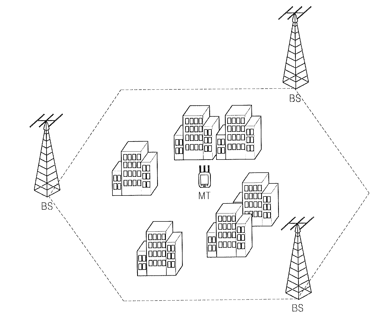
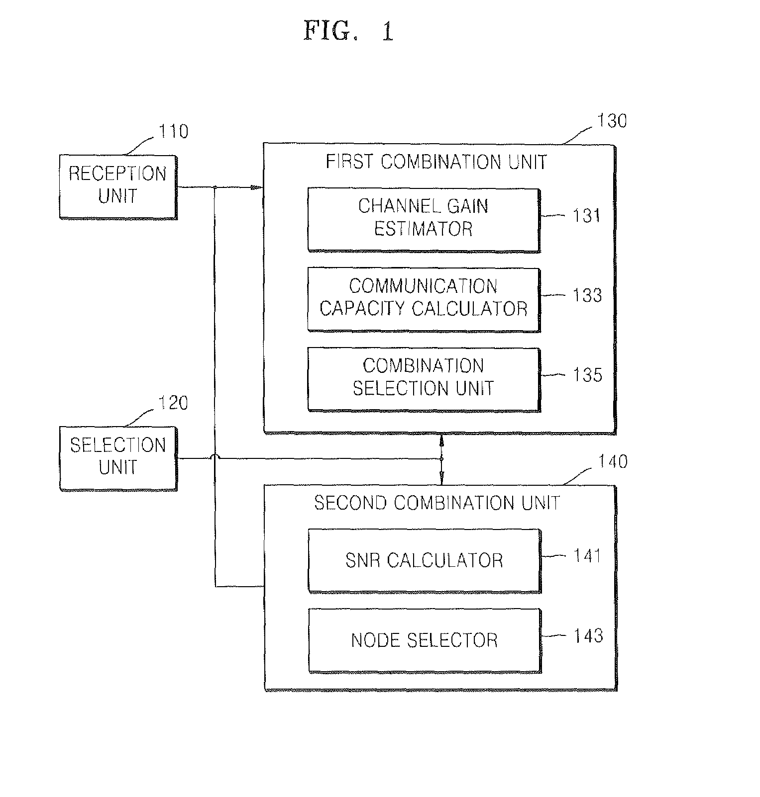
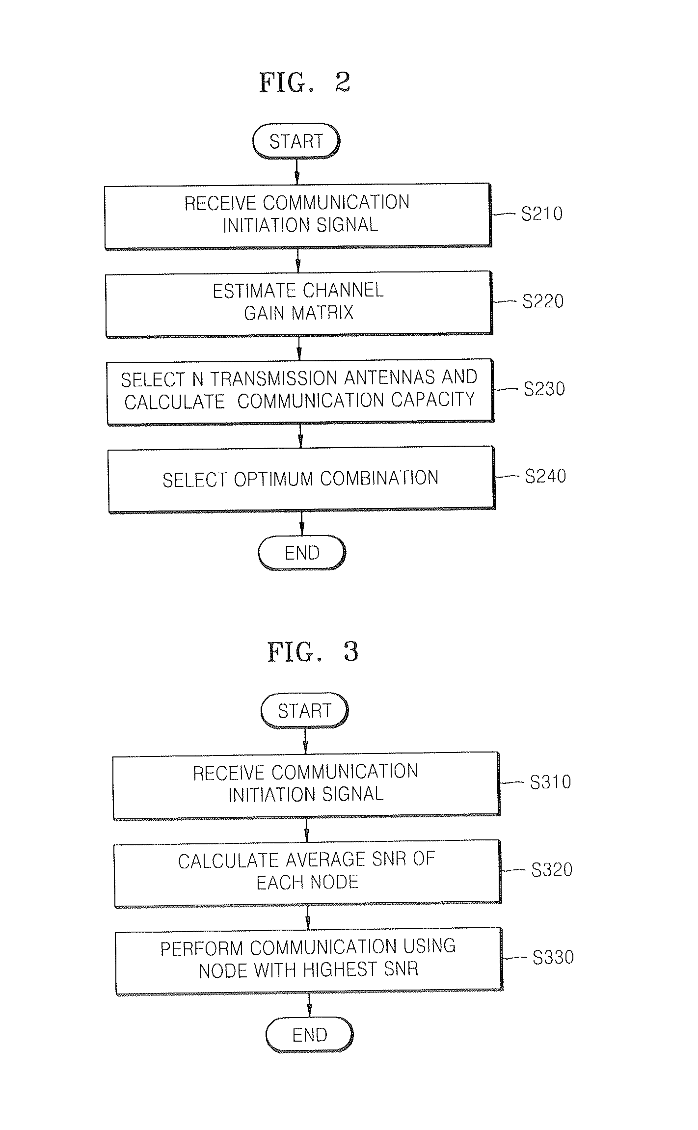
[0020]FIG. 1 is a block diagram of an apparatus for selecting antennas in a multi-input multi-output (MIMO) communication system, according to an embodiment of the present invention, FIG. 2 is a flowchart illustrating a method of selecting antennas in a MIMO communication system, according to an embodiment of the present invention, FIG. 3 is a flowchart illustrating a method of selecting antennas in a MIMO communication system, according to another embodiment of the present invention, FIG. 4 is a schematic diagram illustrating a typical outdoor MIMO communication system equipped with an array antenna, FIG. 5 is a diagram illustrating communication capacity outage performance curves of the MIMO communication system illustrated in FIG. 4, FIG. 6 is a schematic diagram illustrating a MIMO communication system having a macrosc...


PUM


Abstract

An apparatus and method for selecting antennas and nodes in a multi-input multi-output (MIMO) communication system are provided. The apparatus includes a reception unit which detects a communication initiation signal from among a plurality of received signals, a first combination unit which calculates communication capacity based on the communication initiation signal, searches for a combination of transmission antennas that can maximize the communication capacity, and performs communication using the identified combination of transmission antennas, a second combination unit which calculates an average signal-to-noise ratio (SNR) of each node based on the communication initiation signal and selects a node with a highest average SNR and performs communication using the selected node, and a selection unit which activates one of the first combination unit and the second combination unit and inactivates the other combination unit. When the quality of signals transmitted between wireless nodes deteriorates due to a poor channel environment, a node that can minimize the shadowing effect caused by an obstacle that blocks the path of transmission of signals is selected using space diversity. Therefore, it is possible to minimize link communication failures. In addition, it is possible to maximize communication capacity by achieving spatial multiplexing gain using an array antenna that is mounted on a node.

Description

CROSS-REFERENCE TO RELATED PATENT APPLICATION[0001]This application claims the benefit of Korean Patent Application No. 10-2006-0096415, filed on Sep. 29, 2006, in the Korean Intellectual Property Office, the disclosure of which is incorporated herein in its entirety by reference.BACKGROUND OF THE INVENTION[0002]1. Field of the Invention[0003]The present invention relates to an apparatus and method for selecting antennas and nodes so that communication capacity and the reliability of a link during communication between multiple-input multiple-output (MIMO) wireless nodes equipped with two or more antennas (i.e., an array antenna) can be maximized.[0004]2. Description of the Related Art[0005]Multi-input multi-output (MIMO) technology can achieve spatial multiplexing gain and can thus enhance the communication capacity during communication between nodes equipped with array antennas. However, such spatial multiplexing gain can result in high link failure rates due to the deteriorating ...

Claims


Application Information

Patent Timeline
IPC IPC(8): H04B7/02
CPCH04B7/0874H04B7/04H04B7/0413H04B7/088
Inventor JEONG, WUN CHEOLKIM, NAE SOOPYO, CHEOL SIG
Owner ELECTRONICS & TELECOMM RES INST
Why Eureka
Try Eureka