
Automated conveying system

a conveying system and automatic technology, applied in the field of automatic conveying systems, can solve the problems of limited flexibility of the conveying system described, and achieve the effect of preventing slippage or loss of track position

Inactive Publication Date: 2008-04-03
YASKAWA ELECTRIC AMERICA
View PDF12 Cites 35 Cited by
  • Summary
  • Abstract
  • Description
  • Claims
  • Application Information

AI Technical Summary

Benefits of technology

[0018] It is another feature of the invention that the adaptive position-based motion profile-generating algorithm tracks line speed of the input conveyor or the output conveyor, respectively, during transitions to prevent slip or loss of track position.

Problems solved by technology

The described automated conveying system has limited flexibility.

Method used


Image

  • Automated conveying system
  • Automated conveying system
  • Automated conveying system

Examples


Embodiment Construction

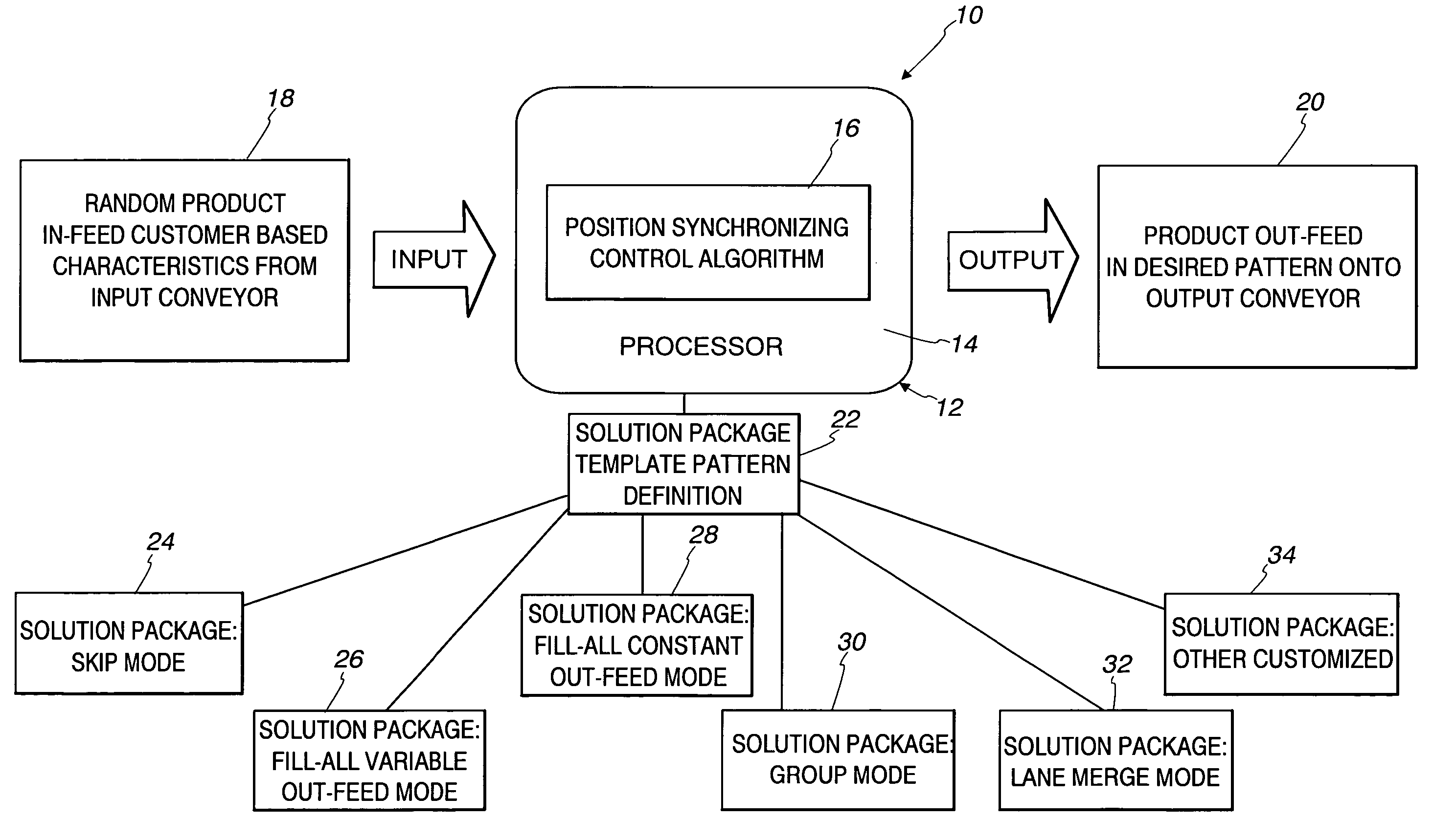
[0028] In accordance with the invention, an automated conveying system uses one or more position controlled conveyance device(s), in series or parallel combinations, that accept randomly spaced product as an input. The system uniquely controls the products relational position by advancing and / or retarding the product position, and then releases the products onto an output conveyor in a desired output pattern. The final output pattern depends on the type of a selected template pattern.

[0029] As used herein, conveyance device is defined as any device or series of devices that transfer product from one location to another, and could include belts, rollers, or other technologies. This document generalizes conveyance devices and will use the term “conveyor” throughout to simplify the description. Servo controlled is defined as any closed loop system that takes feedback to adjust a command reference. The conveyance device may comprise a servo controlled conveyance device, as described he...


PUM


Abstract

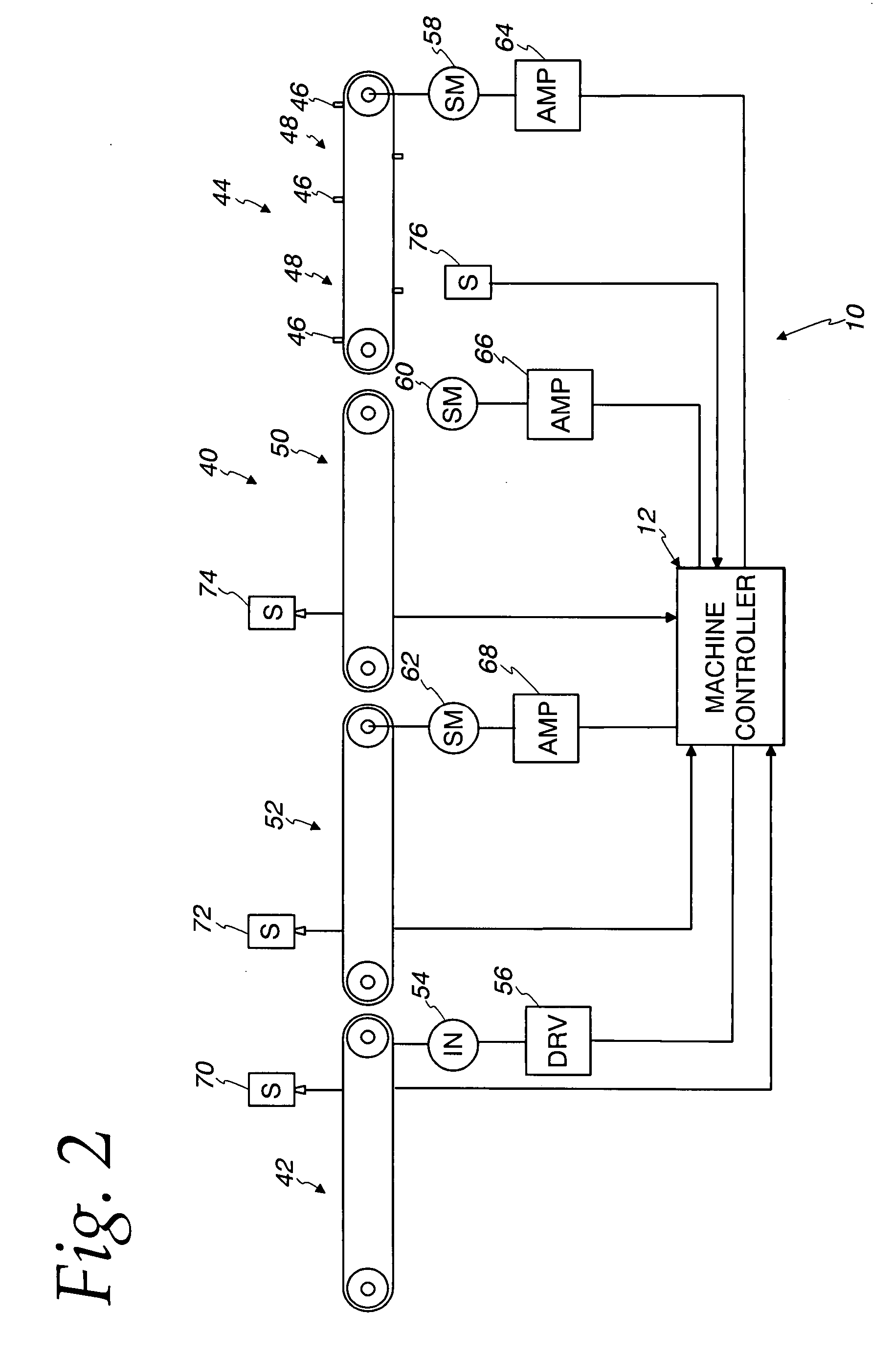
An automated control system is described for a conveying system including an input conveyor supplying a product, a segmented output conveyor delivering a product in a pattern, and one or more synchronizing conveyors disposed between the input conveyor and the output conveyor. The control system comprises a plurality of product position sensors for sensing position of product on each synchronizing conveyor. A conveyor sensor senses segment position of the output conveyor. A plurality of drives, one for each respective conveyor, control the respective conveyors. A database stores a plurality of template pattern algorithms each defining a control algorithm for a distinct product pattern to be delivered from the segmented output conveyor. A controller is operatively connected to the product position sensors, the conveyor sensor and the drives for controlling the conveyors responsive to sensed product position and segment position. The controller includes a programmable processor operable to download a select one of the template pattern algorithms. The controller selectively advances or retards product position relative to the segment position of the output conveyor to release the products onto the output conveyor according to the distinct product pattern defined by the downloaded template pattern algorithm.

Description

CROSS REFERENCE TO RELATED APPLICATIONS [0001] This application claims priority of provisional application No. 60 / 847,756 filed Sep. 28, 2006.FIELD OF THE INVENTION [0002] This invention relates to automated conveying systems and, more particularly, to use of template pattern algorithms to define a desired output pattern. BACKGROUND OF THE INVENTION [0003] A conventional arrayed conveyor system, in one form, is composed of an input conveyor supplying a product, an output conveyor delivering the product and one or more variable speed conveyors between the input conveyor and the output conveyor for performing product position correction. The speed of the output conveyor is fixed and the standard speed of the variable speed conveyor is set to the same speed as the output conveyor. The speed of the variable speed conveyor is assumed to be a select standard speed except when position correction is being implemented. [0004] With such a conveying system, the speed of the input conveyor is ...

Claims


Application Information

Patent Timeline
Patent Type & Authority Applications(United States)
IPC IPC(8): G06F7/00
CPCB65G47/31B65G43/10
Inventor EGAMI, KENGOHULL, KEVIN M.MATSUMOTO, SHUJIFABER, WILLIAM M.
Owner YASKAWA ELECTRIC AMERICA
Learn More