Method and Apparatus for Network Monitoring of Communications Networks

a network monitoring and communications network technology, applied in the field of communication networks, can solve problems such as software failure, hardware failure, and inoperable routers

Inactive Publication Date: 2008-04-03
SIEMENS MEDICAL SOLUTIONS USA INC
View PDF15 Cites 63 Cited by
  • Summary
  • Abstract
  • Description
  • Claims
  • Application Information

AI Technical Summary

Problems solved by technology

Network faults include both hardware failures, such as an inoperative router, and software failures, such as a non-responsive (“hung”) operating system process on a server.
Some network monitoring systems give no indication of whether they are functioning properly or not.
For example, the first indicator of a problem that the network administrator may note is that there have been no recent service updates.

Method used


Image

  • Method and Apparatus for Network Monitoring of Communications Networks
  • Method and Apparatus for Network Monitoring of Communications Networks
  • Method and Apparatus for Network Monitoring of Communications Networks

Examples


Embodiment Construction

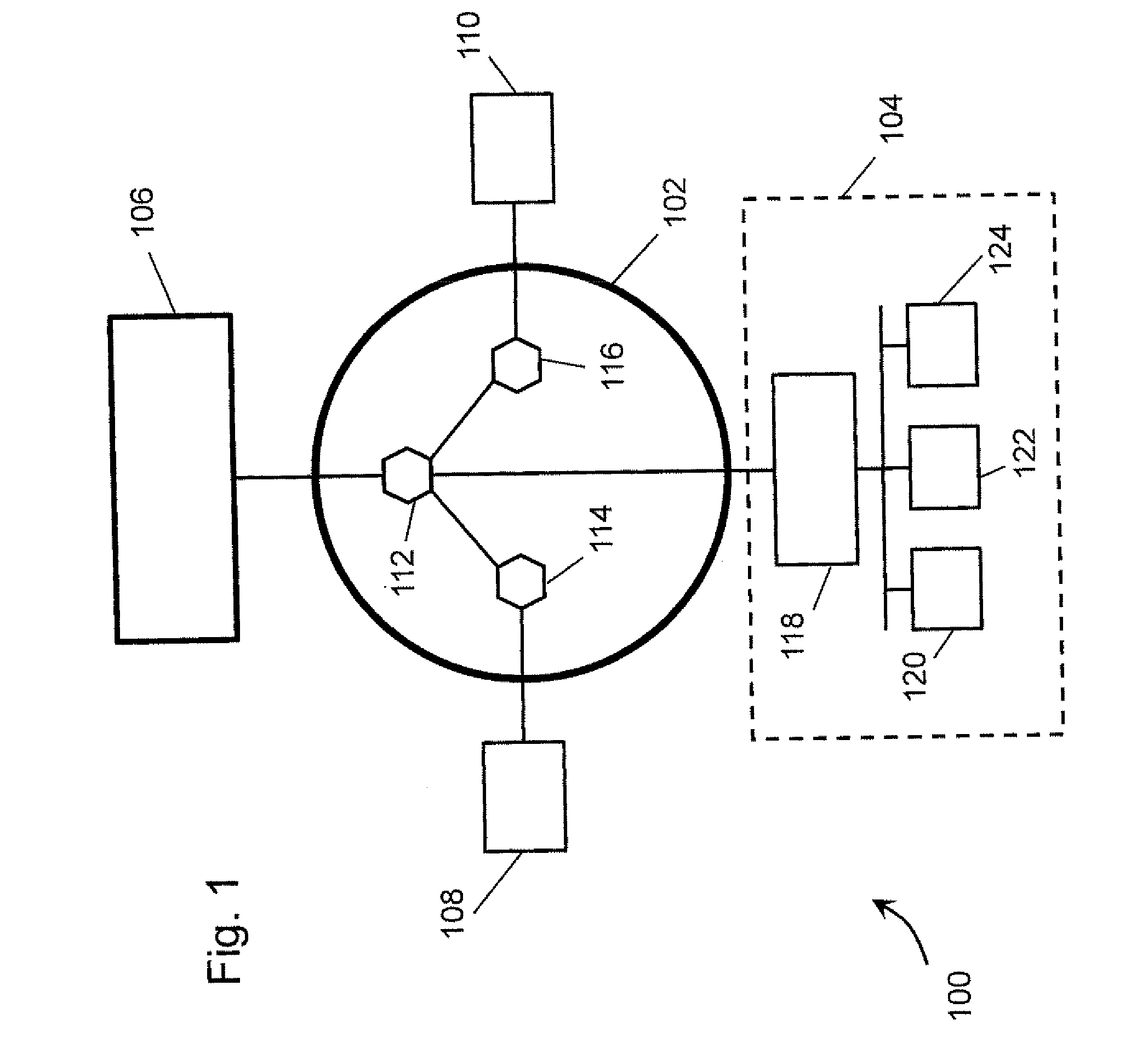
[0019]FIG. 1 shows a high-level schematic of a generic packet data network 100 comprising a wide-area network (WAN) 102 and a local-area network (LAN) 104. Shown in the figure are network elements 106-124. Herein, network element refers to hardware. Network elements 106-110, for example, may represent end-user equipment such as personal computers or workstations. Network elements 112-116, for example, may represent network equipment such as routers and switches. Network element 118, for example, may represent an instrument controller. Herein, a network element may comprise a system. Network elements 120-124, for example, may represent medical systems such as a C-arm X-Ray system, a Magnetic Resonance Imaging system, or a computer-controlled robotic surgical arm. Network elements transmit data to other network elements via data communications links.

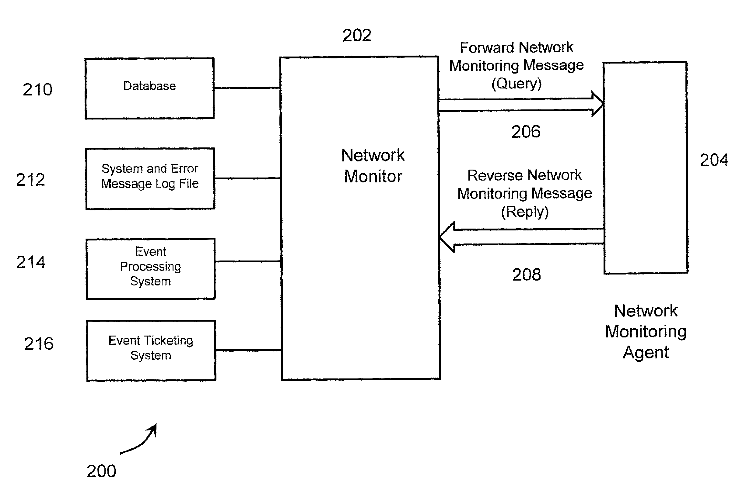
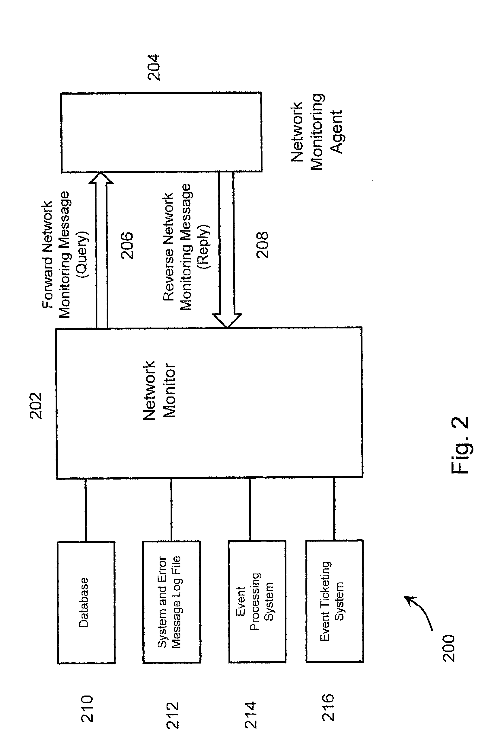
[0020] In commonly deployed network monitoring systems, network monitoring agents reside on network elements. A network monitoring agent...


PUM


Abstract

A network monitor autonomously determines the functional states of a plurality of network monitoring agents loaded on a plurality of network elements. The network monitor sends a query to each network monitoring agent. In response to a query, a network monitoring agent sends a reply back to the network monitor. The reply reports the functional state of the network monitoring agent, operational or non-operational. If the network monitor does not receive a reply back within a timeout interval, it determines that the functional state of the network monitoring agent is non-operational. In an advantageous embodiment, the network monitor autonomously attempts to restart a non-operational network monitoring agent.

Description

[0001] This application claims the benefit of U.S. Provisional Application No. 60 / 827,770 filed Oct. 2, 2006, which is incorporated herein by reference.BACKGROUND OF THE INVENTION [0002] The present invention relates generally to communications networks, and more particularly to network monitoring of communications networks. [0003] Packet data networks may comprise a complex ensemble of network elements (hardware) and associated software. Examples of network elements include network equipment, such as servers, routers, and switches. Other examples include end-user devices, such as personal computers, Voice-Over-IP phones, and cell phones. In a network, software may comprise multiple tiers. Software well known to end-users are end-user applications, such as word processing and database management, and operating systems, such as Windows and Unix. Hidden from most end-users is the network operations software required for a network to function. Network operations software controls the c...

Claims


Application Information

Patent Timeline
Patent Type & Authority Applications(United States)
IPC IPC(8): G06F15/173
CPCH04L41/046H04L43/0805H04L41/0681
Inventor HUBER, MARK A.
Owner SIEMENS MEDICAL SOLUTIONS USA INC
Why Eureka
Try Eureka