Optical disk apparatus and disk rotation speed control method thereof

a technology of optical disk and control method, which is applied in the direction of digital signal error detection/correction, instruments, recording signal processing, etc., can solve the problems of s own uniformity, difficult to inhibit the erroneous detection of the mass eccentricity of the disk, and difficulty in preventing the leaking of tracking error signals, etc., to reduce various kinds of uniformities, reduce leakage of signals, and improve the effect of practical us

Inactive Publication Date: 2008-04-03
HITACHI-LG DATA STORAGE
View PDF3 Cites 17 Cited by
  • Summary
  • Abstract
  • Description
  • Claims
  • Application Information

AI Technical Summary

Benefits of technology

[0016]According to the present invention as was mentioned above, it is possible to achieve the following effects, being superior in practical use thereof, with reducing leakage of the signal into the lens error signal, as well as, reducing various kinds of un-uniformities mentioned above, therefore, it is possible to conduct the disk rotation control with stability, while detecting the mass eccentricity of the optical disk, with certainty, and thereby providing the optical disk apparatus and the disk rotation control method thereof, enabling recording / reproducing of information of high quality onto / from the optical disk.

Problems solved by technology

By the way, although the conventional arts mentioned above, it tries to prevent the tracking error signal from leaking into the lens error signal with the signal processing by means of the band pass filter (BPF), however it is difficult to prevent the tracking error signal from leaking therein at the frequency band where the frequency of the lens error signal can pass through the BPF (i.e., a passing region or band).
Thus, it is difficult to inhibit the erroneous detection of the mass eccentricity of the disk due to the leakage of the tracking error signal into the lens error signal, with certainty.
Also, further, sensitivity and / or vibration characteristics of the lens error signal within each the optical disk apparatus has it's own un-uniformity (i.e., variation), for that reason, there is a problem that accuracy on detection of the mass eccentricity is also un-uniform in the characteristic (i.e., variable).
In particular, in recent years, upon the optical disk apparatus enabling to record / reproduce information onto / from the optical disk, as the information medium, demands are made remarkable for thin-sizing and / or a low pricing, and for that reason, a base mounting thereon a spindle motor for rotationally driving the optical disk is also thin in the thickness thereof or it made of a plastic, etc., therefore un-uniformity factors becomes large on the vibration characteristics or the sensitivity and of the sensitivity of the lens error signal within the optical disk apparatus.
Therefore, with the conventional optical disk apparatus, it is impossible to achieve a stable disk rotation speed control, including the optical disk of such mass eccentricity therein, and there are problems of generation of the noises when the disk rotates at high rotation speed, and instability in the recording / reproducing operation thereof, etc.

Method used


Image

  • Optical disk apparatus and disk rotation speed control method thereof
  • Optical disk apparatus and disk rotation speed control method thereof
  • Optical disk apparatus and disk rotation speed control method thereof

Examples


Embodiment Construction

[0023]Hereinafter, embodiments according to the present invention will be fully explained by referring to the attached drawings.

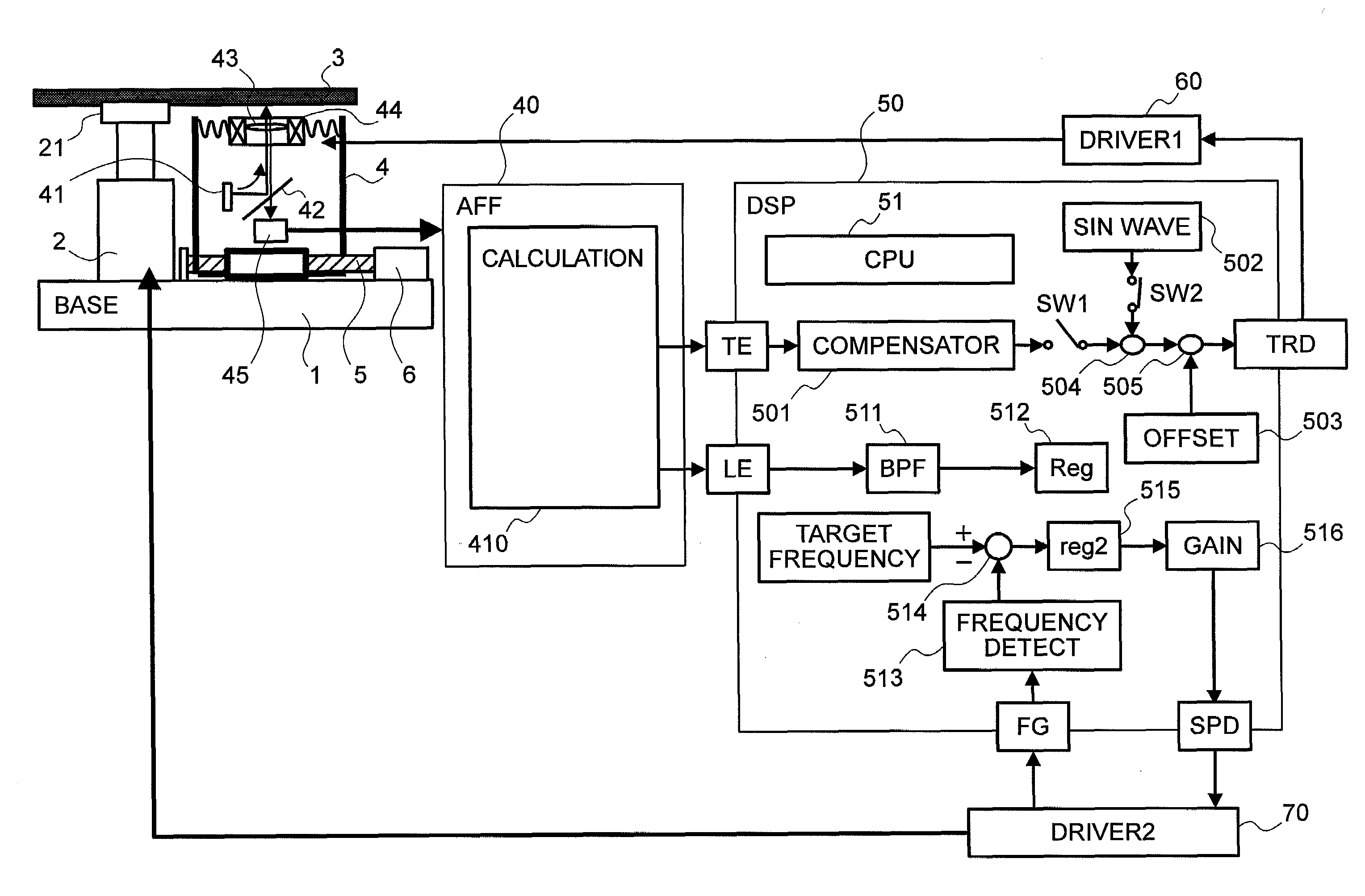
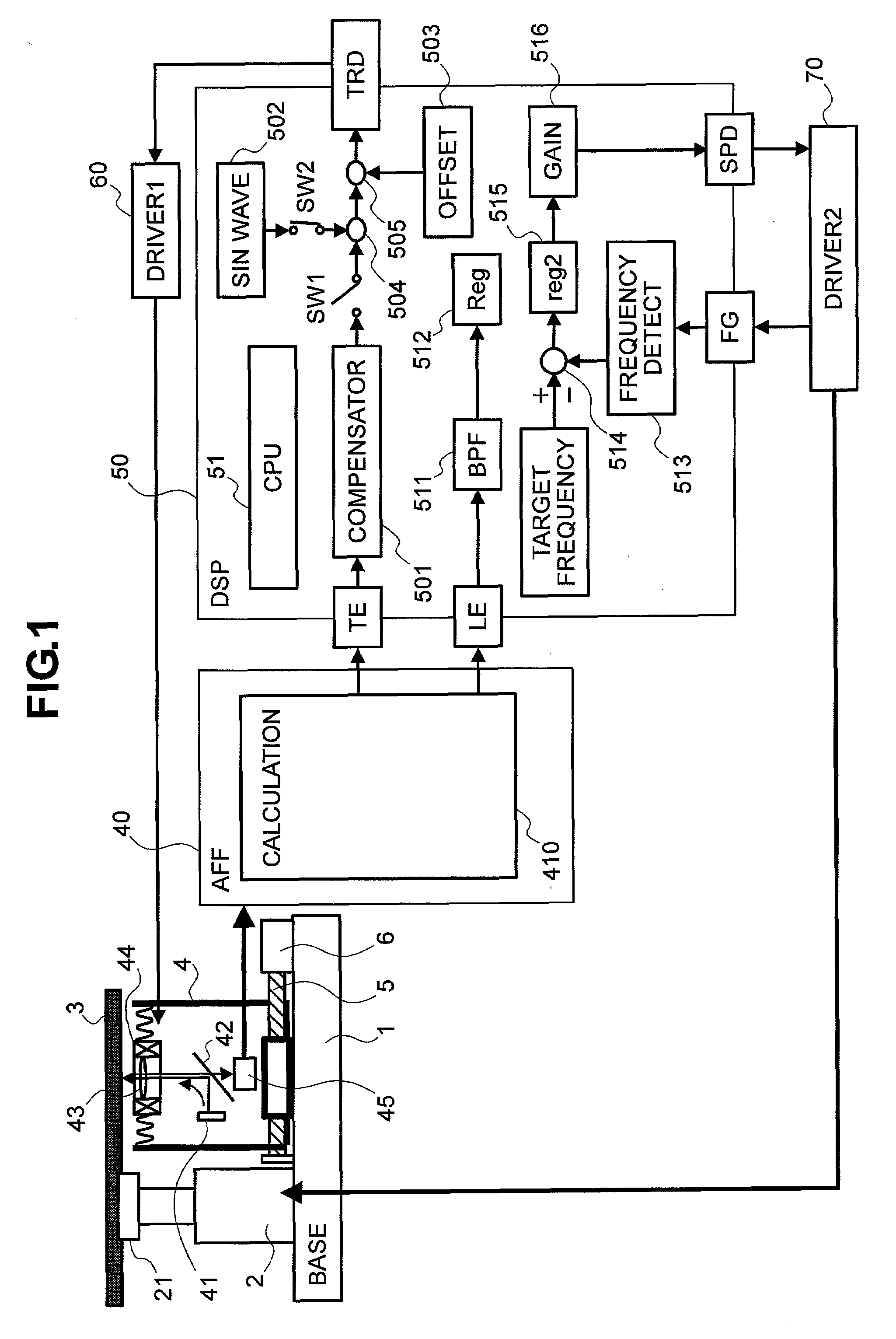
[0024]First of all, FIG. 1 attached herewith shows the inner structures of an optical disk apparatus, according to an embodiment of the present invention, and a reference numeral 1 in this figure depicts a base made of a thin metal plate or a plastic plate, for example, and on this base is mounted a spindle motor 2. On the other hand, onto a turntable 21 attached at a tip of this spindle motor is loaded an optical disk, i.e., an optical information recording medium for enabling recording / reproducing of information onto / from the recording surface thereof, thereby to be rotationally driven at a predetermined speed.

[0025]Also, in neighbor of the spindle motor 2, on this base 1 is attached so-called a pickup, comprising therein a semiconductor laser 41, being a light generating source, a half mirror 42 for guiding a laser beam to a predetermined direction throu...


PUM

PropertyMeasurementUnit
speedaaaaaaaaaa
rotation speedaaaaaaaaaa
frequencyaaaaaaaaaa

Abstract

In an optical disk apparatus and a disk rotation speed control method thereof, enabling to rotate a disk at high speed, with stability and certainty, irrespective of mass eccentricity thereof, detection is made on the greatest value and the smallest value on the signal after conducting a process of a band pass filter 511 on a lens error signal in a step response of a pickup, with using a wobble signal in the place of a tracking error signal and chaining an offset, when controlling the rotation speed of the apparatus by loading an optical disk therein, and thereafter, determination is made on whether the disk rotation speed be shifted to the high speed or not, upon basis of a value obtained through comparison of the maximum value (Max_spnup) and the minimum value (Min_spnup) obtained with the greatest value (Max_step) and said smallest value (Min_step) memorized, when shifting the disk rotation to the high speed.
X=(Maxspnup−Minspnup)/(Max_step−Min_step)

Description

BACKGROUND OF THE INVENTION[0001]1. Field of the Invention[0002]The present invention relates to a method for controlling a disk rotation speed within an optical disk apparatus for recording / reproducing information onto / from an optical information recording medium, and it relates, in particular, to an optical disk apparatus and a disk rotation speed control method thereof, for controlling the rotation speed of an optical disk by taking the mass eccentricity of the optical disk into the consideration thereof.[0003]2. Description of the Related Arts[0004]In an optical disk apparatus enabling to record / reproduce information onto / from an optical information recording medium, such as, an optical disk, for example, recording / reproducing of the information is made by irradiating a laser beam upon the information recording surface thereof, or detecting the reflection light thereon, while rotating the optical disk at high speed. On the optical disk to be rotated at the high speed within such...

Claims


Application Information

Patent Timeline
Patent Type & Authority Applications(United States)
IPC IPC(8): G11B17/03
CPCG11B7/0053G11B19/24G11B17/34
Inventor ITO, MASAMICHIMINODA, HIROSHI
Owner HITACHI-LG DATA STORAGE
Why Eureka
Try Eureka