Eureka AIR delivers breakthrough ideas for toughest innovation challenges, trusted by R&D personnel around the world.

Inductively-coupled plasma torch

Inactive Publication Date: 2008-04-10
NAT INST OF ADVANCED IND SCI & TECH +1
View PDF4 Cites 4 Cited by
  • Summary
  • Abstract
  • Description
  • Claims
  • Application Information

AI Technical Summary

Benefits of technology

[0007] Consequently, the present invention aims to provide an inductively-coupled plasma torch that conveys make-up gas smoothly while holding a capillary tube with a make-up gas tube coaxially, stably and easily, and is capable of easily adjusting the position of the downstream end portion of the capillary tube in the axial direction, when an injector tube is particularly composed of a metallic material.
[0013] The positioning member for positioning the capillary tube in the radial direction can be a guide, for example, having a cylinder-like shape (including a disc-like shape). The guide has a through hole for allowing the capillary tube to penetrate at the central portion thereof. In addition to the through hole, it has a passage groove or a passage hole for conveying make-up gas. The positioning member is mounted and fixed to the downstream end portion of the cylindrical member to hold the capillary tube coaxially to the cylindrical member and also to the make-up gas tube coaxially with the cylindrical member. Thus, it becomes possible to introduce a high-boiling point sample being introduced from the capillary tube into plasma stably with a high efficiency, and the make-up gas also flows smoothly to the downstream end portion of the injector tube. The opening for the make-up gas provided at the positioning member is preferably a passage hole positioned at least at the intermediate position in the radial direction.
[0017] By making the through hole of the positioning member have a diameter slightly larger than the outer diameter of the capillary tube, the outer surface of the capillary tube can be substantially attached firmly to the surface of the through hole. The make-up gas does not substantially flow through the firmly attached portion of the guide and the capillary tube. The use of the positioning member allows the capillary tube to be held on the central axis of the injector tube, that is, coaxially with the injector tube, stably and easily. Further, in order to maintain a relative position of the positioning member to the axial direction of the capillary tube, it is also possible to provide a member for preventing an axial displacement engaging with both of the capillary tube and the positioning member.

Problems solved by technology

However, for conventional apparatuses of these types, it has been difficult to set a sample-introducing tube on the central axis of the inductively-coupled plasma torch, that is, coaxially with it.
For this reason, there has been a problem that, when high-boiling compounds out of the sample-introducing tube are not introduced into the center of inductively-coupled plasma, the sensitivity or accuracy of analysis deteriorates.
However, in such structure, it is considered that the position of the capillary tube changes relative to the inductively-coupled plasma torch to result in a large variation of analytical sensitivity and accuracy.
Consequently, in the case of JP-B 2931967, a part for coaxially arranging a capillary tube to a sample-introducing tube is provided, but the part has such problem that it easily breaks.
In the case of JP-B 3118567, since such part is not provided and a capillary tube easily moves in an injector tube by pressure of the make-up gas, there is such problem that accurate adjustment of the position of the capillary tube in the axial direction is difficult.
However, there is such problem that the injector tube easily breaks.
On the other hand, when an injector tube is composed of a metallic material such as stainless steel, although the function as a guide is fully exerted, it has a rather redundant structure.
Further, in each case, a work of inserting the guide in the vicinity of the downstream end portion of the injector tube and positioning the same is troublesome.

Method used


Image

  • Inductively-coupled plasma torch
  • Inductively-coupled plasma torch
  • Inductively-coupled plasma torch

Examples


Embodiment Construction

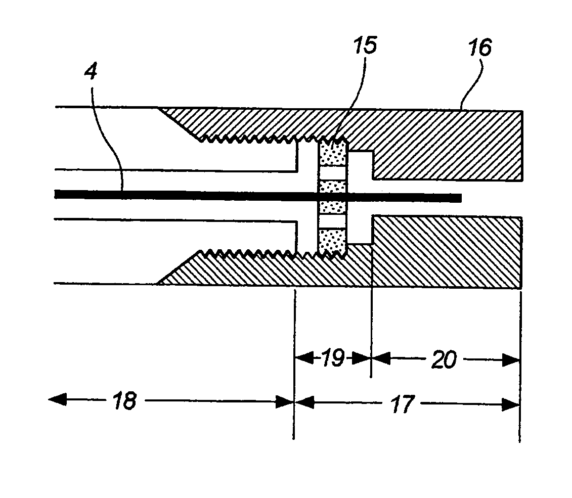
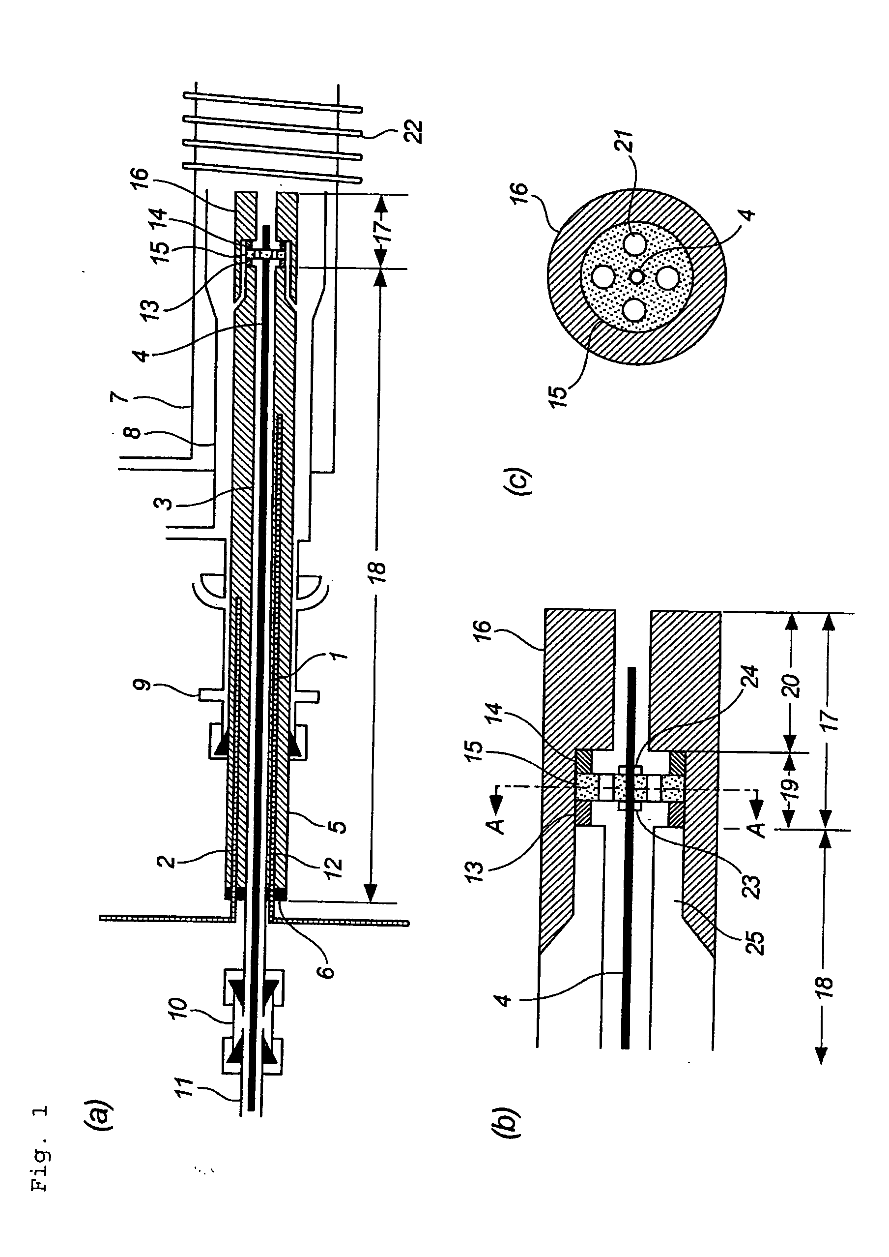
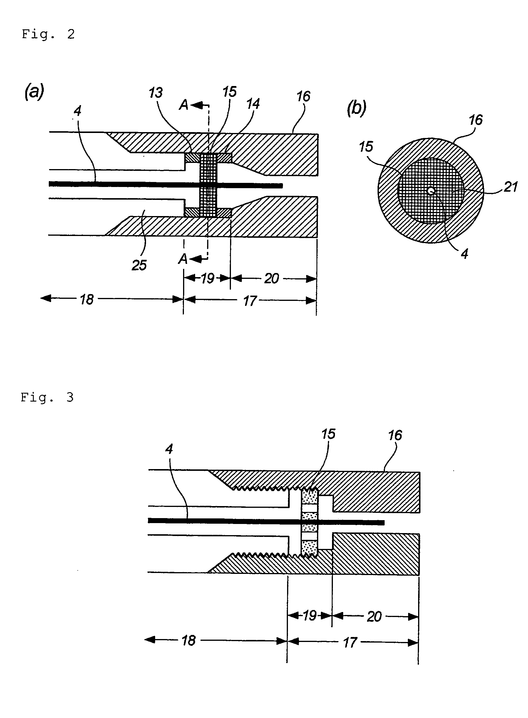
[0023] With reference to the attached drawings, the present invention will be described in further detail. FIG. 1 is a general cross-sectional view showing an inductively-coupled plasma torch of the present invention. FIG. 1(a) shows the whole of the inductively-coupled plasma torch, FIG. 1(b) shows an enlarged cross-sectional view of the downstream end portion in FIG. 1(a), and FIG. 1(c) shows a cross-sectional view taken along the A-A line in FIG. 1(b). A metallic make-up gas tube 3 for conveying make-up gas such as argon (Ar) gas accepts, in the inside thereof, a capillary tube 4 for introducing gaseous molecules of a sample to be analyzed so as to surrounding it. Therefore, the make-up gas tube 3 also has a function for protecting the capillary tube 4 not to be damaged. In the example shown here, the make-up gas tube 3 and the capillary tube 4 are housed in a thermal homogenizing pipe 5 constituted of a heater wire 1, a temperature sensor 2 and a thermal homogenizing material 12...


PUM

PropertyMeasurementUnit
Diameteraaaaaaaaaa
Metallic bondaaaaaaaaaa
Displacementaaaaaaaaaa

Abstract

To provide an inductively-coupled plasma torch capable of holding a capillary tube coaxially with a make-up gas tube stably and easily, smoothly conveying make-up gas and easily adjusting the axial position of the capillary tube downstream end portion. An inductively-coupled plasma torch assembly comprising a make-up gas tube (3) accepting a capillary tube (4) for introducing a gaseous sample so as to surround the capillary tube to allow the make-up gas to pass the space between the capillary tube and the make-up gas tube, a cylindrical member externally heating the make-up gas tube, and torch bodies (7, 8) for supporting the cylindrical member, and being provided with a positioning member (15) for positioning the capillary tube in the radial direction on the downstream end portion side of the cylindrical member, wherein the positioning member is fixed to the downstream end portion of the cylindrical member.

Description

FIELD OF THE INVENTION [0001] The present invention relates to a torch for introducing high-boiling point gaseous molecules into inductively-coupled plasma. In particular, the present invention relates to a torch for effectively introducing high-boiling point gaseous molecules into the center portion of inductively-coupled plasma without cooling and condensing the high-boiling point gaseous molecules, when high-boiling point gaseous molecules, that is, a high boiling point sample to be analyzed in a gaseous molecule state provided from a high temperature source such as a gas chromatograph (GC), a pyrolyzer or a thermogravimeter (TG) is introduced into inductively-coupled plasma (ICP) of an inorganic element analyzer upon carrying out analysis by an inductively-coupled plasma atomic emission spectroscopy (ICP-AES) or an inductively-coupled plasma mass spectroscopy (ICP-MS). RELATED ARTS [0002] Conventionally, in order to introduce high-boiling point gaseous molecules provided from a ...

Claims


Application Information

Patent Timeline
IPC IPC(8): B23K9/00
CPCH05H1/30
Inventor TAO, HIROAKINAKAZATO, TETSUYASAKATA, KENICHI
Owner NAT INST OF ADVANCED IND SCI & TECH
Why Eureka
Eureka Blog
Learn More