Fluid injection device

Active Publication Date: 2008-04-10
SEIKO EPSON CORP +1
View PDF6 Cites 69 Cited by
  • Summary
  • Abstract
  • Description
  • Claims
  • Application Information

AI Technical Summary

Benefits of technology

[0070] By providing a packing, the fluid leakage can be prevente

Problems solved by technology

While the ability to dissect tissues during surgery, for example, is high, the quantity of injection of pulsating fluid was low, and fluid rarely accumulated in the surgical field.
However, even if a pump priming device is installed, the priming device is disconnected and removed after start and when air bubbles are generated in the pump chamber, the drive operation may become unstable.
This check valve

Method used


Image

  • Fluid injection device
  • Fluid injection device
  • Fluid injection device

Examples


first embodiment

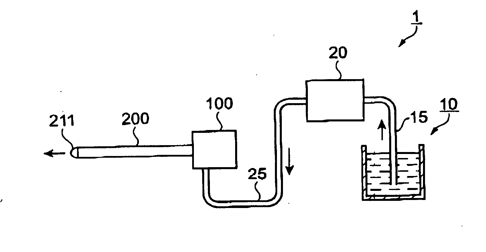
[0093]FIG. 1 is an explanatory schematic diagram of the configuration of the fluid injection device related to the first embodiment of the invention.

[0094] In FIG. 1, the fluid injection device 1 includes a fluid container 10 containing the fluid as the basic configuration, a pump 20 as the pressure generation section, and a pulse generation section 100 generating a pulse flow of the fluid supplied from the pump 20.

[0095] A slender tubular shaped connection flow passage tube 200 is connected to the pulse generation section 100.

[0096] A nozzle 211 with its flow passage compressed is inserted in the front end of the connection flow passage tube 200.

[0097] The flow of the fluid in the fluid injection device 1 is described below in a simple manner.

[0098] The fluid contained in the fluid container 10 is drawn in by the pump 20 through a connection tube 15, and is supplied to the pulse generation section 100 at cornet pressure through a connection tube 25.

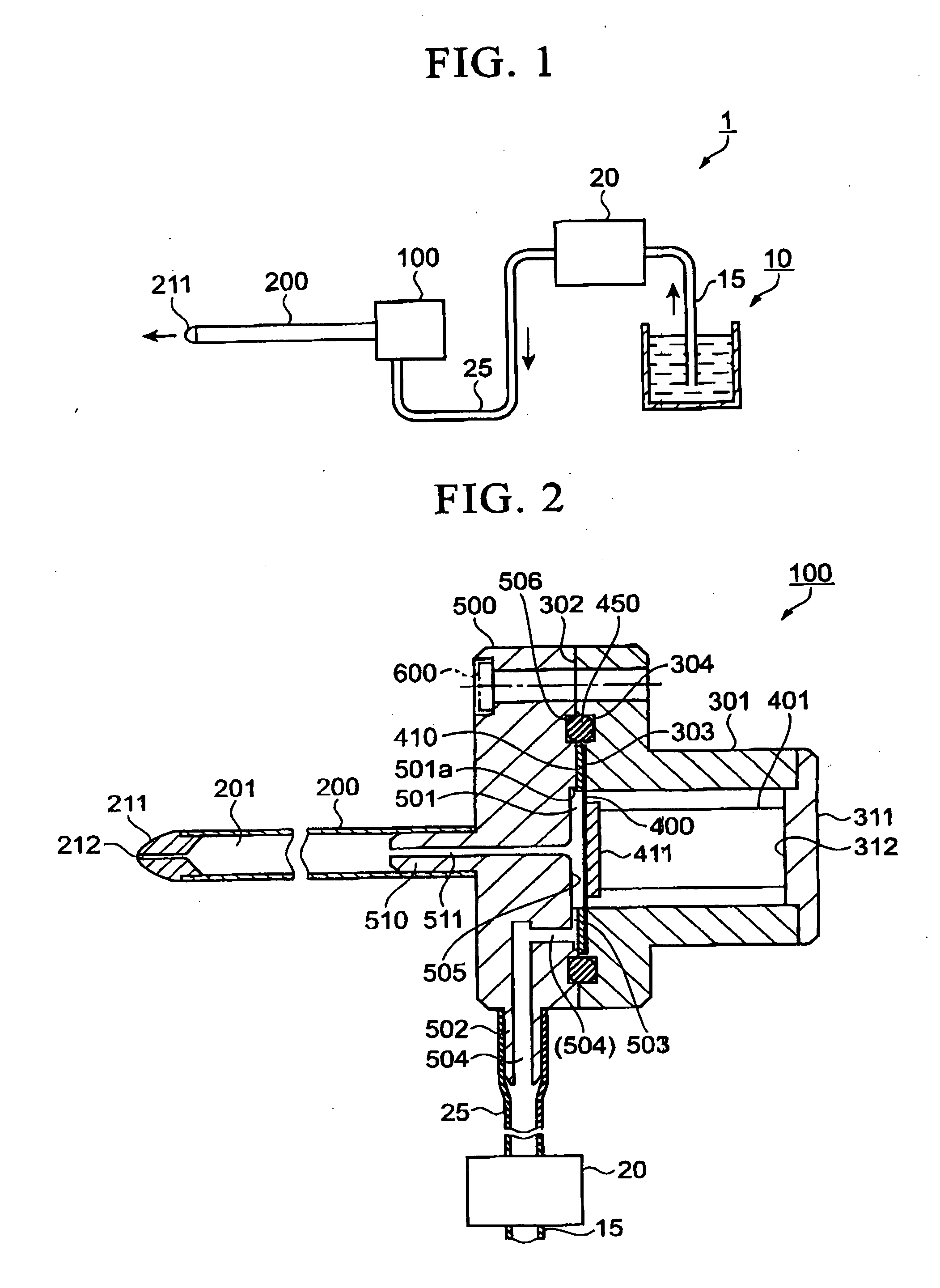
[0099] As shown in FIG. 2, ...

second embodiment

[0211] Next, the pulse generation section related to the second embodiment of the invention is described here referring to the drawings of the same.

[0212] The second embodiment has a swirl flow generation plate including the inner peripheral wall of a fluid chamber and inlet flow passage as the swirl flow generation section.

[0213] Other than the swirl flow generation section, the construction is similar to that of the first embodiment described above, so the explanations are omitted here. The same reference numerals as in the first embodiment are attached to the functional members that are the same in the first embodiment.

[0214]FIG. 4 is a plan view of the swirl flow generation plate 550, and FIG. 5 is a cross-sectional view of the pulse generation section 100 in which the swirl flow generation plate 550 is assembled.

[0215] In FIG. 4, the swirl flow generation plate 550 has an of formed at its central part; however, the peripheral part of this opening has the inner peripheral wa...

third embodiment

[0223] Next, the third embodiment of the invention is described here referring to the drawings.

[0224] The third embodiment has a swirl flow generation plate and diaphragm stacked and attached in intimate contact as an integral body.

[0225] Other than the swirl flow generation section, the construction is similar to that of the second embodiment described above, so the explanations are omitted here. The same reference numerals as in the second embodiment are attached to the functional members that are the same in the second embodiment also.

[0226]FIG. 6 is a plan view of the swirl flow generation plate 550 and the connected diaphragm 400 related to the third embodiment. FIG. 7 is a cross-section view taken along the line A-A shown in FIG. 6.

[0227] The swirl flow generation plate 550 is attached in intimate contact as an integral body with the diaphragm 400 in FIGS. 6 and 7.

[0228] The swirl flow generation plate 550 and the diaphragm 400 may be attached to each other by attaching s...


PUM


Abstract

A fluid injection device includes: a pulse generation section that includes a fluid chamber whose volume is changeable, and an inlet flow passage and an outlet flow passage that are connected to the fluid chamber; a first connection flow passage connected to the outlet flow passage, having an end portion; a second connection flow passage connected to the inlet flow passage; a fluid injection opening formed at the end portion of the first connection flow passage, having a diameter smaller than the diameter of the outlet flow passage; a connection flow passage tube including the first connection flow passage and having rigidity adequate to transmit pules of fluid flowing from the fluid chamber to the fluid injection opening; and a pressure generation section that supplies fluid to the inlet flow passage.

Description

CROSS-REFERENCE TO RELATED APPLICATION [0001] This application claims priority from Japanese Patent Application No. 2006-261114, filed on Sep. 26, 2006, the contents of which are incorporated herein by reference. BACKGROUND [0002] 1. Technical Field [0003] The present invention relates to a fluid injection device. More specifically, the present invention relates to a fluid injection device of simple construction that injects stable and strong pulses of fluid. [0004] 2. Related Art [0005] Conventional fluid injection device as disclosed in the Japanese Unexamined Patent Application, First Publication No. 2005-152127, for example, is well known as a fluid injection device for dissecting or cutting out biopsy tissues. [0006] This fluid injection device includes a micro-pump, a connection flow passage, and a connection tube. [0007] The micro-pump changes the volume of the pump chamber and discharges the fluid. [0008] The outlet flow passage of the micro-pump is connected to one end of t...

Claims


Application Information

Patent Timeline
IPC IPC(8): A61M1/00
CPCA61B17/3203B41J2/17596B41J2/19A61B2017/00154A61B10/02B05B1/086B65D83/00B26F3/004B05B17/0653
Inventor SETO, TAKESHIKAWASUMI, KAZUOTAKAYAMA, KAZUYOSHIHOSSEINI, SEYED HAMID REZA
Owner SEIKO EPSON CORP
Why Eureka
Try Eureka