Open-cycle internal combustion engine

a technology of internal combustion engine and open-cycle, which is applied in the direction of liquid fuel engine, machines/engines, mechanical equipment, etc., can solve the problems of high rotational inertia, high cost of turbo-shaft engine construction, and inability to change the speed of rotation very quickly, so as to improve fuel efficiency, reduce emissions, and reduce operating costs

Active Publication Date: 2008-04-17
VAN BLARICOM TERRY MICHAEL
View PDF29 Cites 9 Cited by
  • Summary
  • Abstract
  • Description
  • Claims
  • Application Information

AI Technical Summary

Benefits of technology

[0016] A primary object of the present invention is to provide an open cycle internal combustion engine with an increased fuel efficiency over open cycle engines of the prior art, reducing emissions and lowering operating costs.

Problems solved by technology

This is largely because a turbo-shaft engine is expensive to build, as much as ten times as expensive as reciprocating engines of the same horsepower.
Additionally, the turbo-shaft engine cannot change its speed of rotation very quickly.
This is because the rotating components are driven at very high speeds causing a high rotational inertia.
This high rotational inertia also causes a danger when failure of a rotating component occurs, because the energy that is stored in the high speed rotating parts can be very difficult to contain.
The use of a regenerator adds even more bulk and cost to the system.
Unfortunately, the high velocity of the hot gasses causes a major energy loss due to friction and turbulence, with the parasitic friction loss increasing generally as the square of the velocity.
Again, there is a substantial energy loss due to the turbulence and parasitic drag caused by these high gas speeds.
In comparison, the gasses flow relatively freely through the blades of a turbine type of power section, losing useful energy in turbulence and drag as they are vectored from blade to blade.
As previously mentioned, the turbo-shaft engine is available only at a very high cost, which limits its use to military and commercial aircraft, military conveyances such as tanks and ships, and large electrical power plants, where the costs of acquisition and the provision of regeneration is not so much at issue.
In addition to the high cost of the exotic materials required in the turbo-shaft engine, additional costs are incurred due to the turbo-shaft engine's high rotational speeds, which require special bearings and lubrication systems, with no tolerance for error in manufacturing.

Method used


Image

  • Open-cycle internal combustion engine
  • Open-cycle internal combustion engine
  • Open-cycle internal combustion engine

Examples


Embodiment Construction

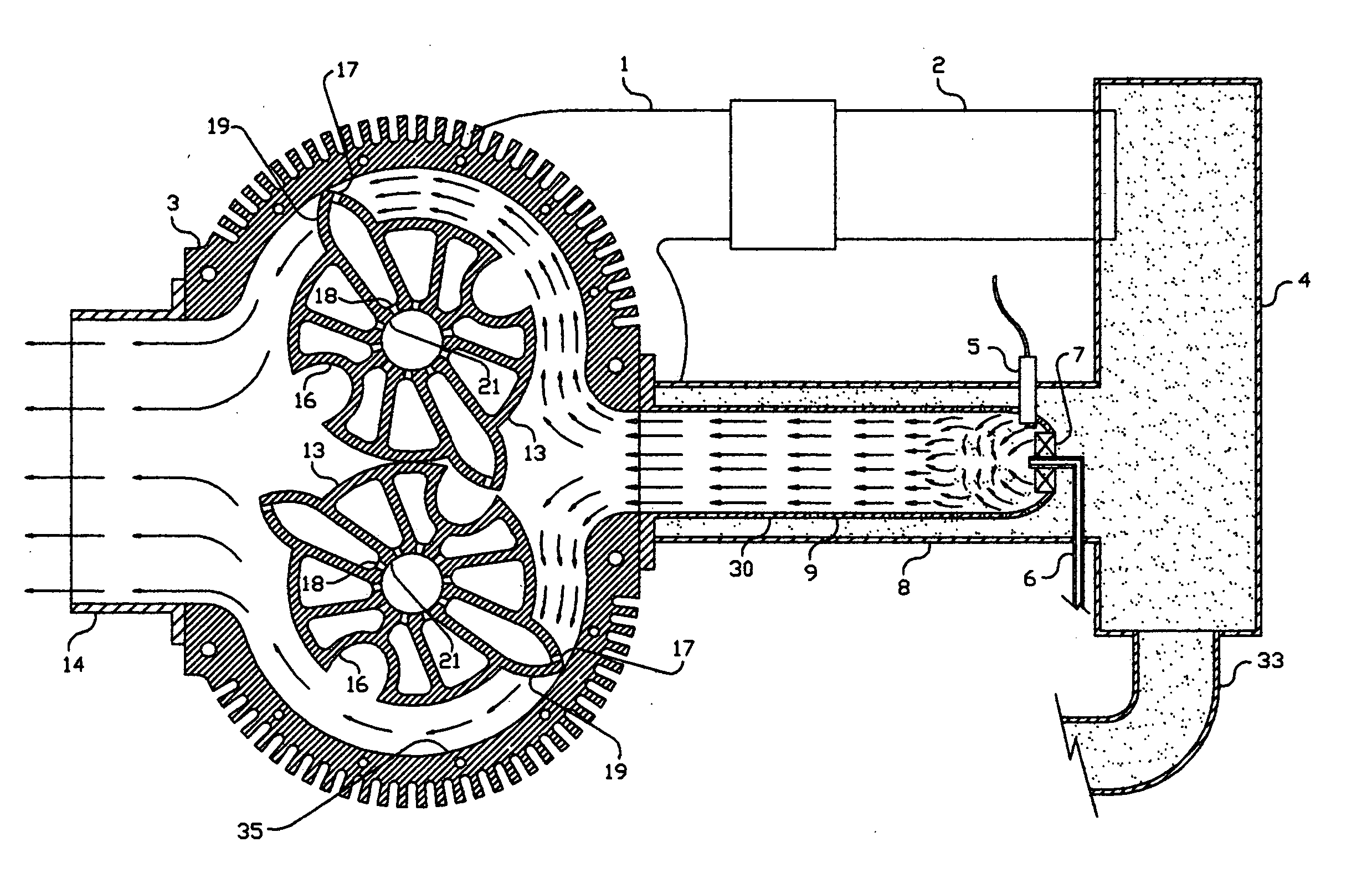
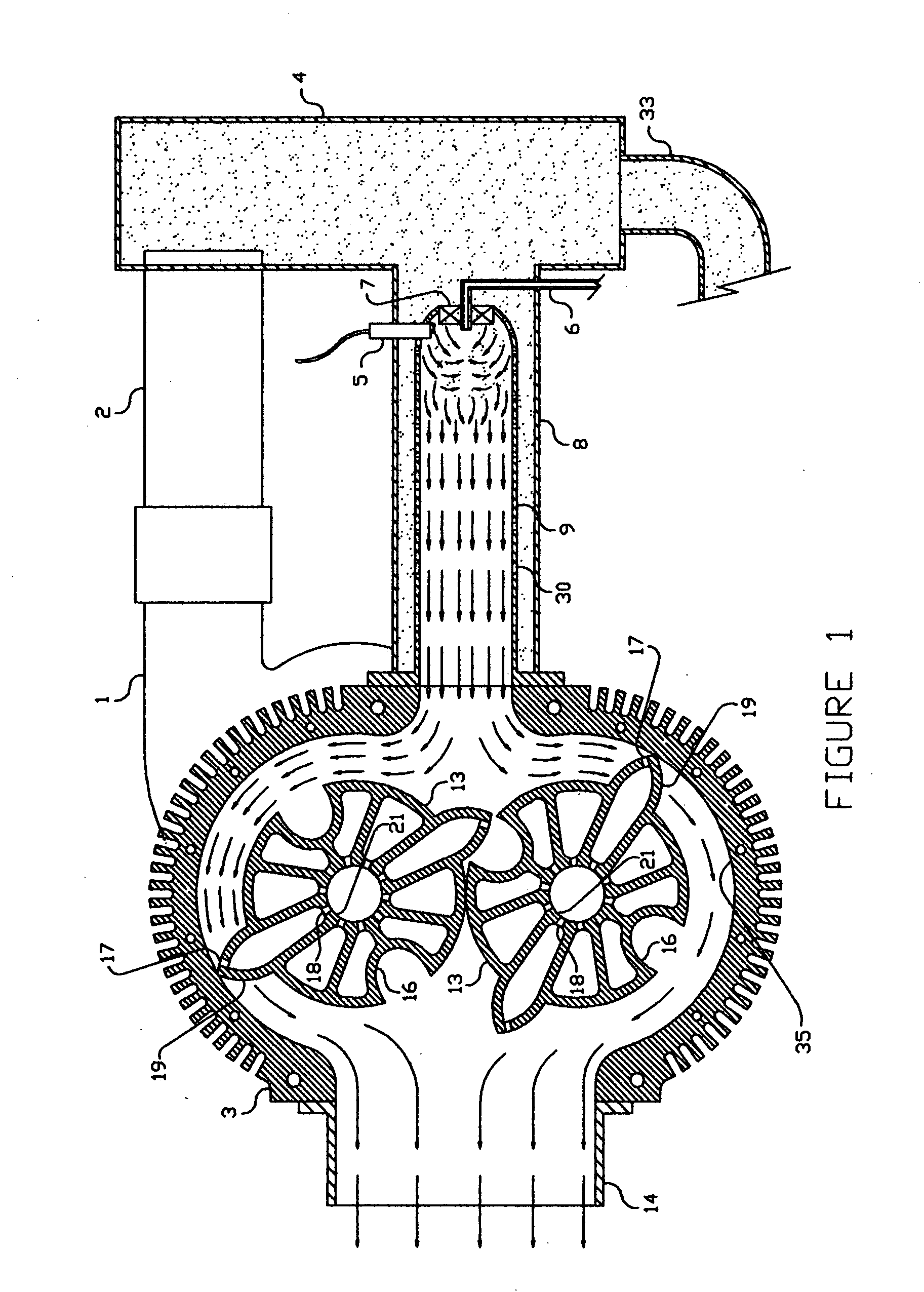
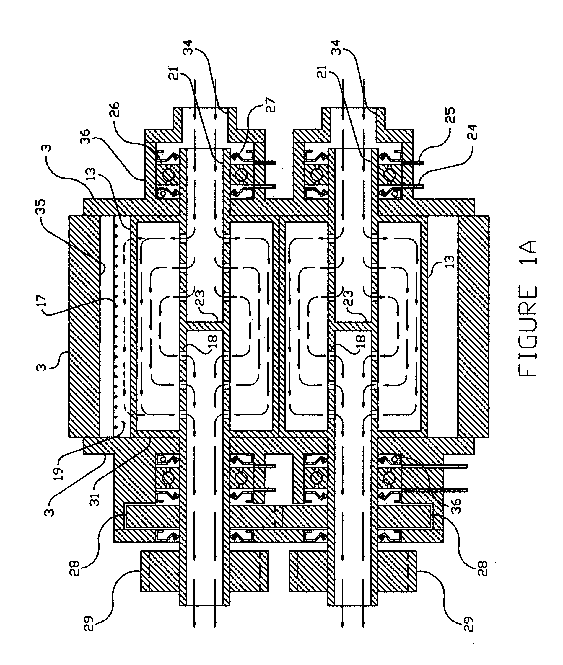
[0027]FIGS. 1 and 1A show cross-sections of the preferred embodiment of an open cycle internal combustion engine of the present invention. The FIG. 1 section is taken on a line through the mid-point of the rotors 13, combustion chamber liner 9, and plenum 4. The rotor shaft plugs 23, shown in FIG. 1A, are not depicted in this view. The FIG. 1A section is taken on a line taken longitudinally through the centers of the hollow rotor shafts.

[0028] In operation;

[0029] A centrifugal compressor 1, driven by a drive gear 29 on one of the rotor shafts 21, forces compressed air through a compressed air duct 2 and into a plenum 4. The plenum 4 transfers the compressed air to a burner shroud 8, which conducts the compressed air to a swirler 7, and a burner liner 9. Fuel is introduced into the combustion area by a fuel-metering nozzle 6, which is fed by a fuel-metering pump, which is of conventional design and not shown. The swirler creates turbulence to mix the compressed air homogeneously wi...


PUM


Abstract

An open-cycle engine in which rotary power is produced by the pressure of hot gasses against confined, rotating vanes.

Description

[0001] This application is based on provisional application U.S. Ser. No. 60 / 841,918, filing date Sep. 5, 2006.FIELD OF THE INVENTION [0002] This invention is an improved internal combustion engine of the Brayton, or open cycle type. An open cycle engine may be defined as an internal combustion engine in which the compression of air and the burning of fuel when mixed with the compressed air, takes place continuously. [0003] Jet turbine engines that produce shaft power may best represent open cycle engines of the prior art. Engines of this type are called turbo-shaft engines, and are typically used to power helicopters and larger fixed-wing aircraft because they are efficient, lightweight, clean-burning, have a multi-fuel capability, and spin smoothly with no reciprocating parts. BACKGROUND OF THE INVENTION [0004] The aforementioned attributes notwithstanding, the turbo-shaft engine is not generally utilized to provide power in common conveyances such as boats, motorcars and, trucks....

Claims


Application Information

Patent Timeline
Patent Type & Authority Applications(United States)
IPC IPC(8): F01D1/24
CPCF01C1/123Y02T50/671F02C3/00Y02T50/60F02K3/00F02C3/107F02C3/14F01D5/02
Inventor VAN BLARICOM, TERRY MICHAEL
Owner VAN BLARICOM TERRY MICHAEL
Why Eureka
Try Eureka