
Drive System And An Axle For A Vehicle Driveline, And A Vehicle Comprising The Driveline

Inactive Publication Date: 2008-04-17
VOLVO CONSTR EQUIP
View PDF5 Cites 6 Cited by
  • Summary
  • Abstract
  • Description
  • Claims
  • Application Information

AI Technical Summary

Benefits of technology

[0008] It is desirable to achieve a drive system and an axle for a vehicle driveline, which improves the control of the driveline with regard to delivery of drive torque to the ground engaging members.
[0010] Preferably, said clutch is gradually engagable so that it permits, in an active state, different relative rotational speeds between an input member and an output member of the clutch. Thus, each clutch is configured to permit different degrees of slip. This creates conditions for a dynamic control of the drive line.
[0015] According to a preferred embodiment, the drive system comprises a longitudinal clutch arranged for engaging and disengaging, respectively, the second (and third) wheel axle from a driving connection with the main gear box. By disconnecting said longitudinal clutch, only the first (front) wheel axle is in driving connection with the engine. Thus, the wheels of the second (and third) axle would rotate, however not the central transmission in the axle. This would give an energy-efficient driving, especially advantageous for transporting material longer stretches.
[0016] A further purpose of the invention is to achieve a method for controlling the power delivered to a plurality of ground engaging members of a vehicle driveline, which improves the control of the driveline with regard to delivery of drive torque to the ground engaging members.
[0017] This purpose is achieved with a method according to the following claim 27. Further advantageous embodiments and further advantages of the invention emerge from the detailed description below and the claims.

Problems solved by technology

However, this characteristic of delivering approximately equal amounts of torque to the drive wheels independently of their relative rotational speed significantly limits the total amount of torque which can be delivered to the drive wheels when one of the drive wheels loses traction.

Method used


Image

  • Drive System And An Axle For A Vehicle Driveline, And A Vehicle Comprising The Driveline
  • Drive System And An Axle For A Vehicle Driveline, And A Vehicle Comprising The Driveline
  • Drive System And An Axle For A Vehicle Driveline, And A Vehicle Comprising The Driveline

Examples


Embodiment Construction

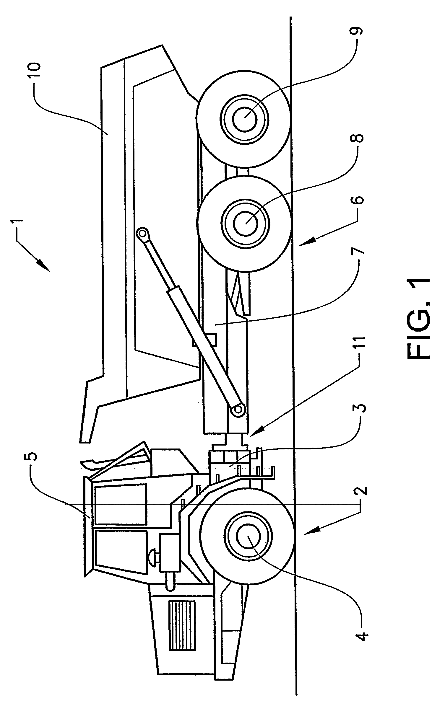
[0025]FIG. 1 illustrates a frame-steered work vehicle in the form of an articulated hauler 1. The articulated hauler 1 comprises a forward vehicle section 2 comprising a forward frame 3, a front wheel axle 4 an engine (not shown) for propelling the vehicle and a cab 5. The articulated hauler 1 also comprises a rear vehicle section 6 comprising a rear frame 7, a forward bogie axle 8, a rear bogie axle 9 and a tiltable load-carrying platform 10.

[0026] The forward frame 3 is connected to the rear frame 7 by means of an articulation joint 11 allowing the forward vehicle section 2 and the rear vehicle section 6 to pivot relative to one another about a vertical axis. A pair of hydraulic cylinders (not shown) is arranged one on each side of the articulation joint 11 and controlled by an operator via a steering wheel and / or a joy stick (not shown) for steering of the vehicle. The articulation joint 11 is further configured for allowing the forward vehicle section 2 and the rear vehicle sec...


PUM


Abstract

The invention relates to a drive system for a vehicle driveline comprising a pair of interconnected first transverse drive shafts (31a, 31b) extending in opposite directions, each of which supports a ground engaging member, and a first arrangement (101) allowing said pair of first transverse drive shafts to rotate at different speeds. Said arrangement (101) comprises a pair of individually selectively engagable clutches (37a, 37b), one clutch for each transverse drive shaft, and each of said clutches (37a, 37b) is configured for engaging and disengaging, respectively, the associated transverse drive shaft (31a, 31b) to a driving connection with a source of motive power.

Description

BACKGROUND AND SUMMARY [0001] The present invention relates to a drive system for a vehicle driveline comprising a pair of interconnected first transverse drive shafts extending in opposite directions, each of which supports a ground engaging member, and an arrangement allowing said pair of first transverse drive shafts to rotate at different speeds. The invention also relates to an axle comprising said pair of transverse drive shafts for a vehicle driveline and a vehicle comprising the driveline. [0002] The invention will below be described for a frame-steered work vehicle in the form of an articulated hauler. This should however be regarded as a non-limiting example. The invention may also be applied in other frame-steered work vehicles, like a wheel loader, backhoe loader, tractor and other types of work vehicles, like an excavator or a skid steer vehicle. The term “ground engaging member” is used for drive wheels or caterpillar tracks. The invention may further be applied in a p...

Claims


Application Information

Patent Timeline
IPC IPC(8): B60K17/354
CPCB60K17/165B60K17/34B60Y2200/148B60K23/0808B60K17/3515
Inventor ANDERSSON, THOMASSTRANDBERG, JONNYWARGH, CHRISTIAN
Owner VOLVO CONSTR EQUIP
Features
  • Generate Ideas
  • Intellectual Property
  • Life Sciences
  • Materials
  • Tech Scout
  • Unparalleled Data Quality
  • Higher Quality Content
  • 60% Fewer Hallucinations
Learn More