
System and Method for Automatic Steering

a technology of automatic steering and automatic steering, applied in the direction of steering components, non-vehicle mounted steering controls, vehicles, etc., can solve the problems of erratic steering, problems such as problems in retrofitting a conventional automatic steering actuator system to a hydrostatic steering system, and not as successful on hydrostatic steering agricultural vehicles

Inactive Publication Date: 2008-04-17
ACCUTRAK SYST
View PDF12 Cites 22 Cited by
  • Summary
  • Abstract
  • Description
  • Claims
  • Application Information

AI Technical Summary

Benefits of technology

[0012]In typical operation, a hydrostatic drive uses pressurized hydraulic fluid to drive a right wheel and a left wheel of a vehicle. The hydraulic fluid is routed by a valve block to a right hydraulic motor that is connected to and rotates a right wheel of the vehicle and to a left hydraulic motor that is connected to and rotates a left wheel of the vehicle. To drive the vehicle in a straight line, the same amount of hydraulic fluid flow is directed to both the right hydraulic motor and left hydraulic motor, causing the right wheel and left wheel to rotate at the same velocity. To turn the vehicle to the right, more hydraulic fluid flow is directed to the left hydraulic motor causing the left drive wheel of the vehicle to rotate faster than the right drive wheel. Alternatively, the vehicle can be turned to the right by decreasing the fluid flow to the right hydraulic motor causing the right drive wheel to rotate slower than the left wheel. To turn the vehicle to the left, either more hydraulic fluid is routed to the right hydraulic motor or less to the left hydraulic motor, causing the right drive wheel to rotate faster in relation to the left drive wheel.
[0013]The steering system of the present invention connects into the conduits routing hydraulic fluid to the right hydraulic motor and left hydraulic motor. To turn the vehicle to the right, the steering system diverts hydraulic fluid flow away from the right hydraulic motor causing the right wheel to rotate slower and the vehicle to turn to the right. To turn the vehicle to the left, the steering system diverts hydraulic fluid flow away from the left hydraulic motor causing the left drive wheel to rotate slower and the vehicle to turn to the left.
[0014]The steering system turns the vehicle in response to control signals from a control system. The control system can be any of the control systems as known in the prior art that is operative to determine a position of the vehicle and compare it to a desired path. If the vehicle has deviated from a desired path, the control system sends control signals to the steering system that causes the vehicle to turn to the right or left as required to move the vehicle back to the desired path. As the vehicle is turning, the control system will continue, at set intervals, to determine the position of the vehicle and once the vehicle has turned a sufficient amount so that it is once again on the desired path, the control system will stop sending control signals to the steering system and the steering system will stop diverting hydraulic fluid away from the hydraulic fluid motors, causing the steering system to stop turning the vehicle. In some cases where a substantial correction to the direction of travel has been made, the control system may need to turn the vehicle in the opposite direction for a short period of time to straighten it out on the desired path.

Problems solved by technology

While these prior art systems have proven themselves workable on standard steering systems, they have not been as successful on agricultural vehicles that have hydrostatic steering.
Trying to retrofit a conventional automatic steering actuator system to a hydrostatic steering system has been problematic.
Routing this highly pressurized hydraulic fluid in a hydrostatic system to the outside drive wheel to cause the vehicle to turn results in erratic steering and unsatisfactory operation of these auto-steer systems.

Method used


Image

  • System and Method for Automatic Steering
  • System and Method for Automatic Steering
  • System and Method for Automatic Steering

Examples


Embodiment Construction

:

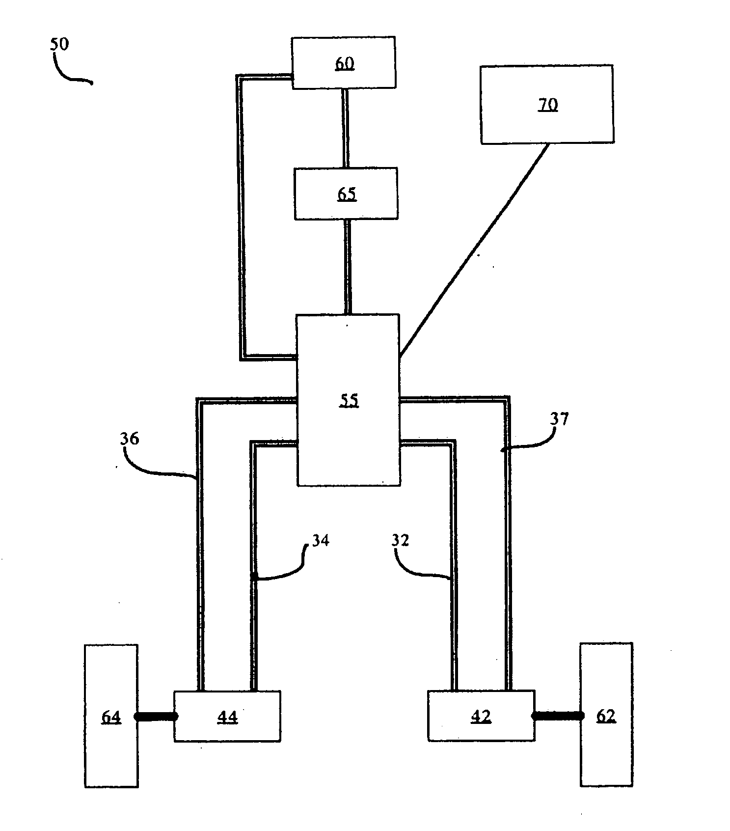
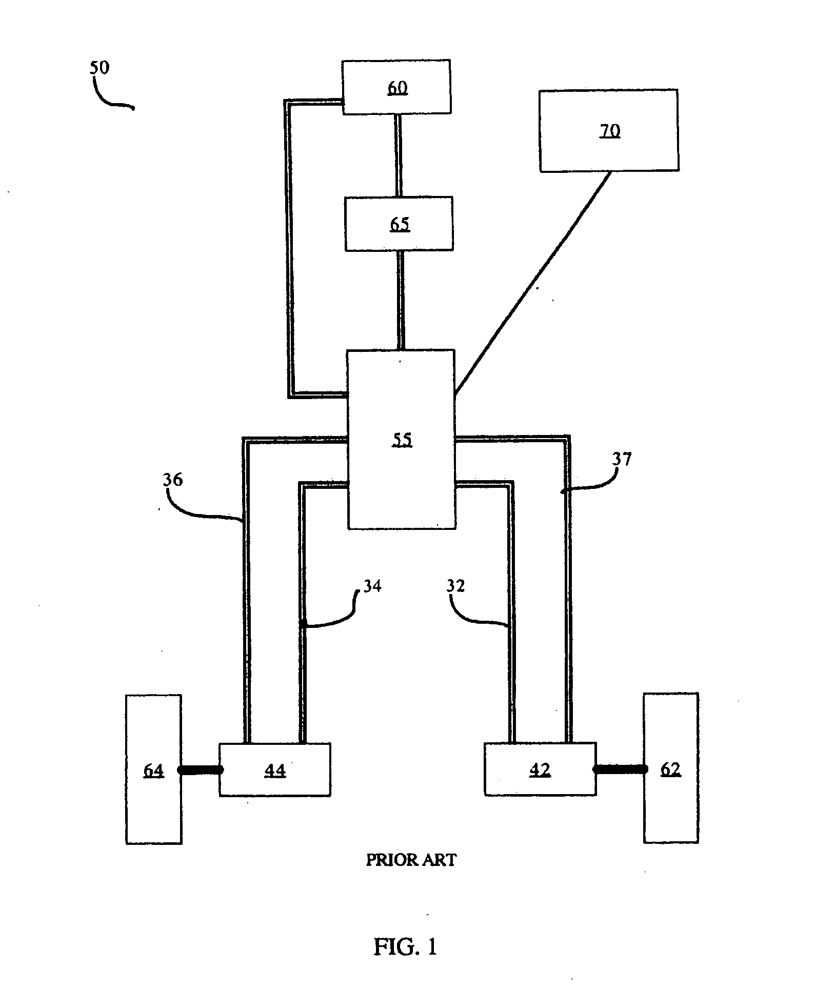
[0021]FIG. 1 is a schematic illustration of a conventional hydrostatic drive system of a vehicle as known in the prior art. A conventional hydrostatic drive system, such as the hydrostatic drive system 50 comprises: a right hydraulic motor 44; a left hydraulic motor 42; a right drive conduit 34; a right return conduit 36; a left drive conduit 32; a left return conduit 37; a valve block 55; a tank 60; a pump 65 and a manual steering control 70.

[0022]In typical operation of the hydrostatic drive system 50, hydraulic fluid from the tank 60 will be pressurized by the pump 65 and the pressurized hydraulic fluid routed to the valve block 55. The valve block 55 is a hydraulic circuit that can selectively vary the flow of hydraulic fluid. From the valve block 55, this pressurized hydraulic fluid is routed through the right drive conduit 34 to the right hydraulic motor 44 to drive a right wheel 64, connected to the right hydraulic motor 44. From the right hydraulic motor 44, the hydraulic f...


PUM


Abstract

An apparatus and method for automatically steering a vehicle with hydrostatic steering is provided. The vehicle has a right hydraulic motor and a left hydraulic motor connected to right and left drive wheels, respectively. A pressurized hydraulic fluid source supplies a hydraulic fluid flow to the hydraulic motors, driving the wheels. A control valve system can divert a portion of a hydraulic fluid flow to either the right or left hydraulic motor, in response to a control signal from a control system, causing the hydraulic motor to slow the rotation of the connected wheel, turning the vehicle. The vehicle is automatically steered by the control system determining a steering direction required to steer the vehicle and causing a portion of a hydraulic fluid flow to a hydraulic motor driving a wheel of the vehicle to be diverted, slowing the wheel and steering the vehicle.

Description

[0001]This invention is in the field of control equipment for vehicles with hydrostatic drives and more specifically for control systems incorporating auto-steering capabilities.BACKGROUND[0002]There are numerous control systems on the market that can determine a desired vehicle path of an agricultural vehicle and then invoke a vehicle steering actuator system to maintain the agricultural vehicle along the desired vehicle path. Typically, these control systems are used to guide an agricultural vehicle on a desired path, for planting, spraying harvesting, etc. First, a desired path in a field to be planted, sprayed, harvested, etc. is determined by the control system and the control system will then attempt to cause the agricultural vehicle to move in a desired adjacent path after each pass of the agricultural vehicle making more ideal adjacent paths.[0003]These control systems typically comprise a microprocessor and require some type of input that allows the control system to determ...

Claims


Application Information

Patent Timeline
Patent Type & Authority Applications(United States)
IPC IPC(8): B60K17/10G06F19/00
CPCA01B69/008B60W30/10B62D11/06B62D11/005B62D11/02B62D1/28
Inventor PALMER, RON
Owner ACCUTRAK SYST
Features
  • Generate Ideas
  • Intellectual Property
  • Life Sciences
  • Materials
  • Tech Scout
  • Unparalleled Data Quality
  • Higher Quality Content
  • 60% Fewer Hallucinations
Learn More