Interactive display using planar radiation guide

a technology of radiation guide and interactive display, applied in the direction of instruments, lighting and heating apparatus, optical elements, etc., can solve the problem that the planar light guide is not used in an interactive display

Active Publication Date: 2008-04-17
MICROSOFT TECH LICENSING LLC
View PDF9 Cites 21 Cited by
  • Summary
  • Abstract
  • Description
  • Claims
  • Application Information

AI Technical Summary

Benefits of technology

[0010]This Summary is provided to introduce a selection of concepts in a simplified form that are further described below in the Detailed Description. This Summary is not intended to identify key features or essential features of the claimed subject matter, nor is it intended to be used as an aid in determining the scope of the claimed subject matter.

Problems solved by technology

However, the planar light guide is not used in an interactive display that integrates both display and imaging functionalities.

Method used


Image

  • Interactive display using planar radiation guide
  • Interactive display using planar radiation guide
  • Interactive display using planar radiation guide

Examples


Embodiment Construction

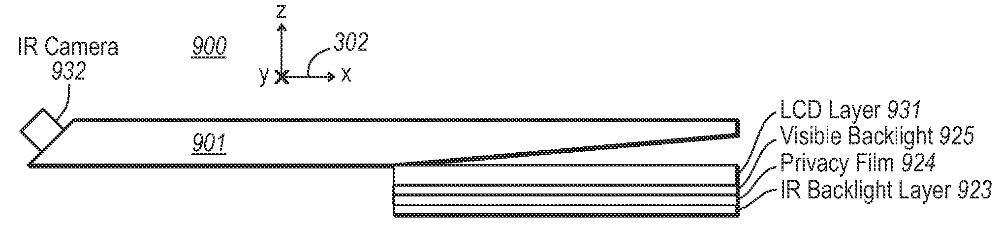
[0025]Embodiments of the present invention extend to an interactive display that performs both display and imaging operations. At least one of the display and imaging operations uses a planar radiation guide (i.e., a “planar light guide” if the radiation is light). The planar radiation guide may be quite thin, and can be used to control where radiation is emitted (and / or detected if used to image) by the planar radiation guide. Accordingly, a thin interactive display is enabled in which objects in contact with (or in front of) the display may be imaged to provide input to the system. Accordingly, the display and imaging interfaces may be co-located.

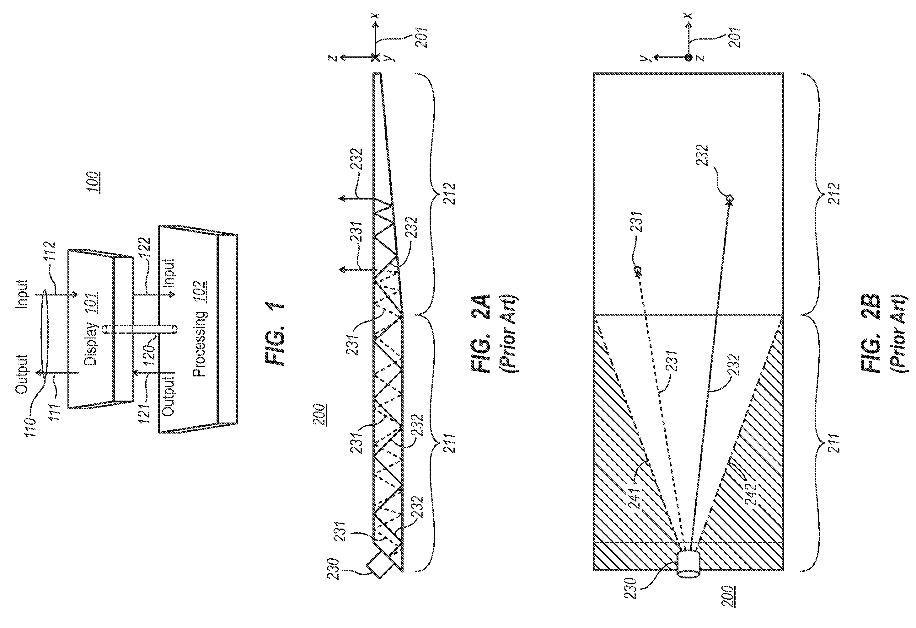
[0026]FIG. 1 schematically illustrates a general system 100 that includes a display 101 and processing components 102 that are interconnected as represented by connection 120. The processing components 102 may process information using hardware, software, or a combination of hardware and software.

[0027]When information is to be displayed ...


PUM


Abstract

An interactive display that uses a planar radiation guide (such as a planar light guide) to perform display and/or imaging. The planar radiation guide has a radiation propagation portion and a radiation interface portion. The radiation propagation portion propagates the radiation by the principles of total internal reflection (with perhaps some minor leakage). The planar radiation guide also has a radiation interface portion where radiation is more apt to exit or enter the planar radiation guide. The interactive display performs both display and imaging, while the planar radiation guide is used to perform at least one (but perhaps both) of the display and imaging operations.

Description

BACKGROUND[0001]The functionality of many computing systems relies on effective display of information using a display. More recently, the display has also been used as a direct input device. For instance, a display might be equipped with touch sense resistive and / or capacitive arrays to detect a portion of the display being contacted.[0002]Displays may also be equipped with a camera system that is positioned at some distance behind the display. The camera focuses on objects closer to the display to allow for visual input to the computing system by having the computer visually detect objects interacting with the display. Such “vision capture” technology relies on the presence of some distance between the display panel and the camera system placed behind the display. These vision capture systems are thus quite large, but are quite acceptable for many applications such as projection systems in which the thickness of the display is not critical.[0003]Recently, technology has been made ...

Claims


Application Information

Patent Timeline
Patent Type & Authority Applications(United States)
IPC IPC(8): F21V7/04
CPCG02B6/0046G02B6/0051G06F2203/04109G06F3/0425G02B6/0053G02F1/1333G03B21/00G06F3/0304G06F3/0412
Inventor BATHICHE, STEVEN N.SILVERSTEIN, DANA LU
Owner MICROSOFT TECH LICENSING LLC
Why Eureka
Try Eureka