Organic-Complex Thin Film For Nonvolatile Memory Applications

a nonvolatile memory and complex technology, applied in the field of organic composite materials, can solve the problems of strict evaporation conditions and requirements

Inactive Publication Date: 2008-04-17
RGT UNIV OF CALIFORNIA
View PDF47 Cites 13 Cited by
  • Summary
  • Abstract
  • Description
  • Claims
  • Application Information

AI Technical Summary

Problems solved by technology

However, most of the organic thin films are fabricated by thermal evaporation in high vacuum and the requirements for the evaporation conditions are very strict.

Method used


Image

  • Organic-Complex Thin Film For Nonvolatile Memory Applications
  • Organic-Complex Thin Film For Nonvolatile Memory Applications
  • Organic-Complex Thin Film For Nonvolatile Memory Applications

Examples


example

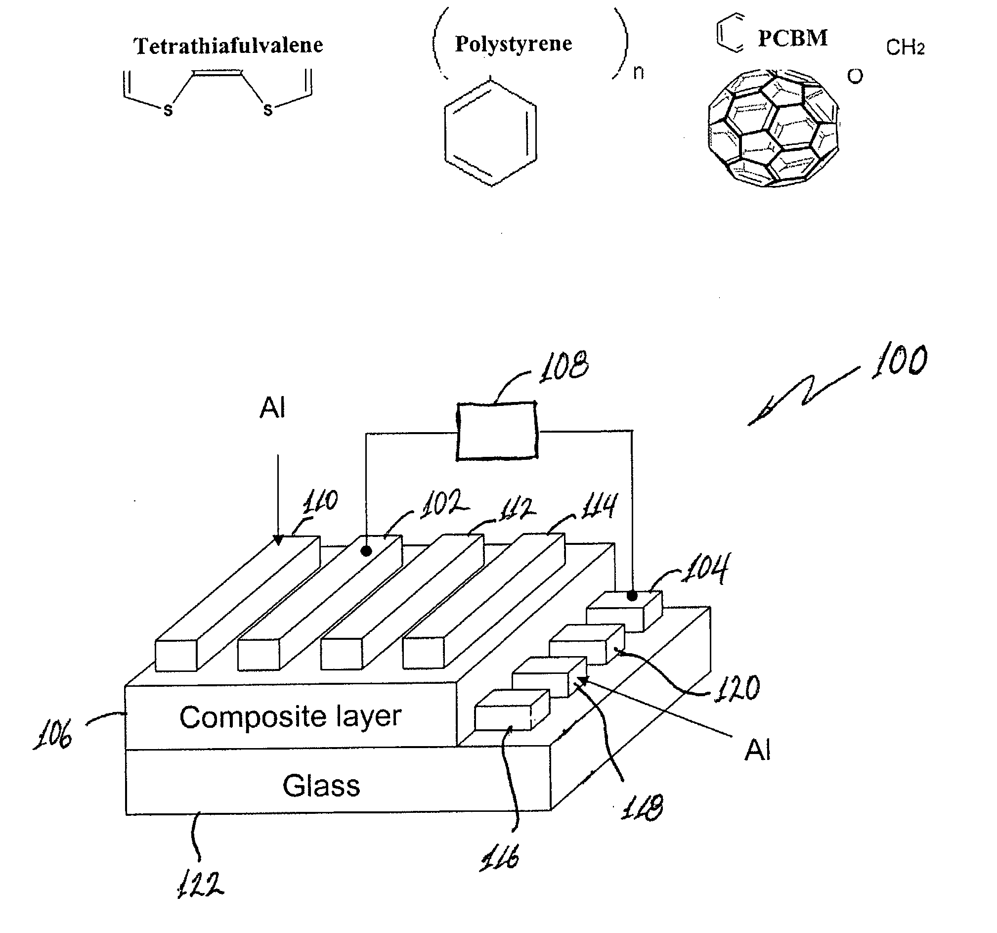
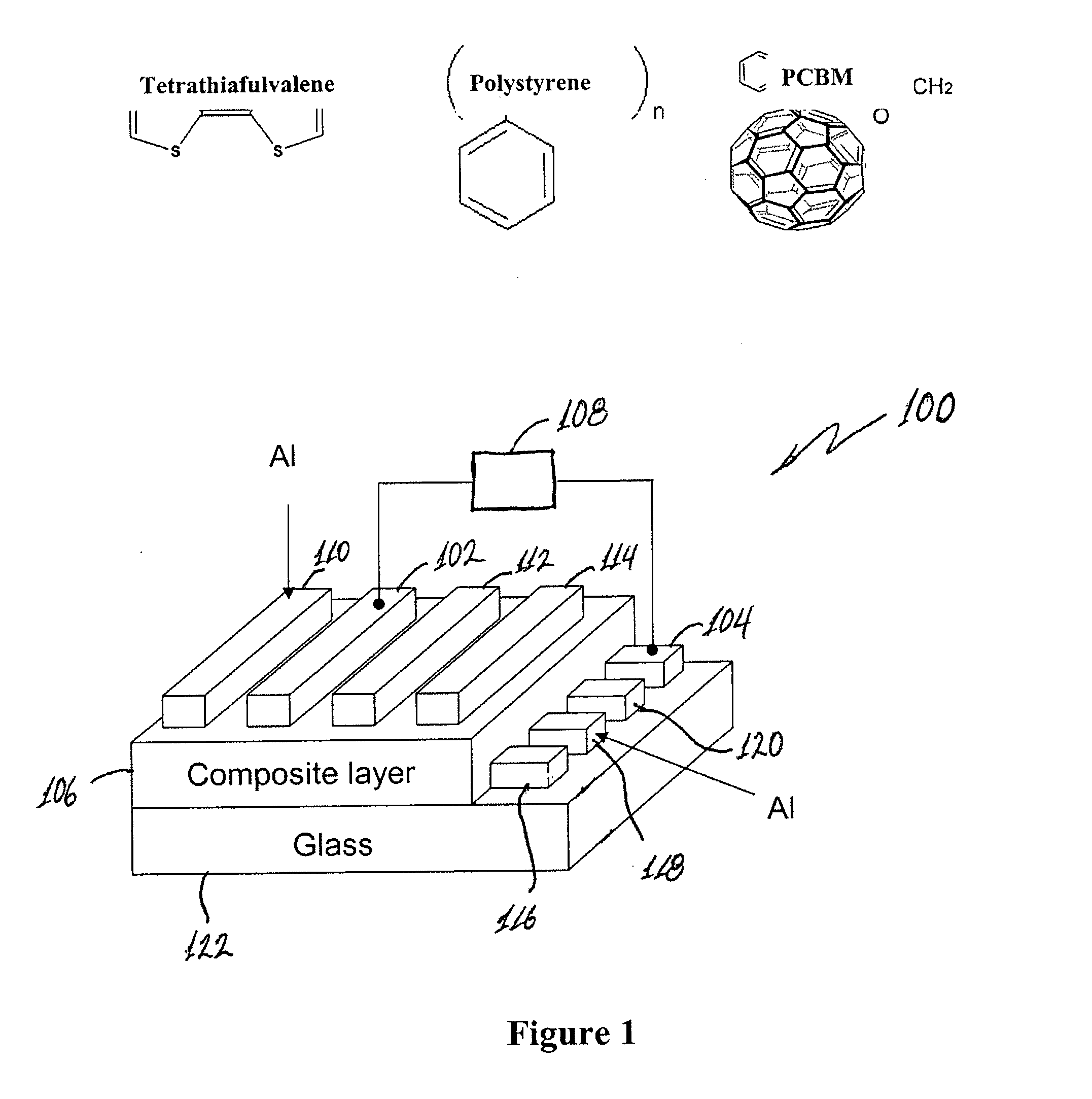
[0024] Examples of chemical structures of the materials of the device of the embodiment of FIG. 1 are indicated in FIG. 1. The device fabrication procedure involves deposition of aluminum (Al) 0.2 mm in width and 75 nm in thickness on thoroughly cleaned glass substrates to form the bottom electrode by thermal evaporation under vacuum (below 6×10⁻⁶ Torr) in this example. Before spin-coating the composite layer, the substrates were exposed to UV-ozone treatment for 15 min. Then, the polymer film was formed by spin-coating 1,2-dichlorobenzenic solution of 1.2 wt. % polystyrene and 0.8 wt. % TTF and 0.8 wt. % PCBM. Good results have been obtained by using amounts of electron acceptor (PCBM) and electron donor (TTF) to be about the same. However, the relative amounts may vary. In addition good results were obtained using weight ratios of polymer matrix (PS):electron acceptor (PCBM):electron donor (TTF) in a range of about 1:1:1 to 10:1:1.

[0025] The deposited film was thermally annealed ...


PUM

PropertyMeasurementUnit
widthaaaaaaaaaa
widthaaaaaaaaaa
thicknessaaaaaaaaaa

Abstract

An electronic or electro-optic device according to an embodiment of this invention has a first electrode, a second electrode spaced apart from the first electrode, and an organic composite layer disposed between the first electrode and the second electrode. The organic composite layer is composed of an electron donor material, an electron acceptor material, and a polymer matrix material. The organic composite layer exhibits substantial bistability of an electrical property.

Description

CROSS-REFERENCE OF RELATED APPLICATION [0001] This application claims priority to U.S. Provisional Application No. 60 / 623,721 filed Oct. 28, 2004, the entire contents of which are hereby incorporated by reference.BACKGROUND [0002] 1. Field of Invention [0003] The present invention relates to an organic composite material having bistability of an electrical property, electronic or electro-optic devices having the organic composite material and methods of use. [0004] 2. Discussion of Related Art [0005] In recent years, organic electronic devices have been replacing inorganic-dominated electronic and opto-electronic devices, such as light emitting diodes C. W. Tang and S. A. VanSlyke, Appl. Phys. Lett. 51, 913, (1987), R. H. Friend, R. W. Gymer, A. B. Holmes, J. H. Burroughes, R. N. Marks, C. Taliani, D. D. C. Bradley, D. A. Dos Santos, J. L. Bredas, M. Logdlund, and W. R. Salaneck, Nature 397, 121 (1999), solar cells N. S. Sariciftci, L. Smilowitz, A. J. Heeger and F. Wudl, Science 25...

Claims


Application Information

Patent Timeline
Patent Type & Authority Applications(United States)
IPC IPC(8): G11C11/00H01B1/12
CPCB82Y10/00G11C13/0014G11C13/0016G11C13/0069H01L51/0591G11C2213/15G11C2213/77H01L51/0051G11C2013/009H10K85/611H10K10/50G11C11/34H10K85/10H10K85/111H10K85/113H10K85/115H10K85/114H10K85/211H10K85/60H10K85/615
Inventor YANG, YANGOUYANG, JIANYONGCHU, CHIH-WEI
Owner RGT UNIV OF CALIFORNIA
Why Eureka
Try Eureka