In-Line Pipe Inspection Tool

a technology of inspection tool and pipe, which is applied in the direction of pipe elements, structural/machine measurement, and magnetic measurement, etc., can solve the problems of not being able to adapt to pipelines of different diameters, requiring a high force to move the pipeline pig along the pipe, etc., and achieves improved sizing accuracy, small error in defect sizing accuracy, and more accurate inspection

Inactive Publication Date: 2008-04-24
PII LIMITED
View PDF7 Cites 42 Cited by
  • Summary
  • Abstract
  • Description
  • Claims
  • Application Information

AI Technical Summary

Benefits of technology

[0037]The magnetic field in the pipe wall is dependent on the wall thickness. If the permanent magnet is designed to provide an adequate field for inspection in a thicker walled pipe, then the field in a thin walled pipe will be considerably higher. Whilst this does not prevent inspection of such a thin walled pipe, control of the pipe wall field may permit more accurate inspection to be achieved. For example, if the dynamic range of the electronic circuitry controlling the sensors is limited, an excessive field can result in electronic saturation or “clipping” of the signals of the electronic circuit. Thus, by controlling the field to be lower in a thin walled pipe, it is possible to ensure that all signals a

Problems solved by technology

However, such an arrangement has the problem that it cannot then adapt to pipelines of different diameters, and to other features of pipeline such as mitred bends, valves, etc.
However, the use

Method used


Image

  • In-Line Pipe Inspection Tool
  • In-Line Pipe Inspection Tool
  • In-Line Pipe Inspection Tool

Examples


first embodiment

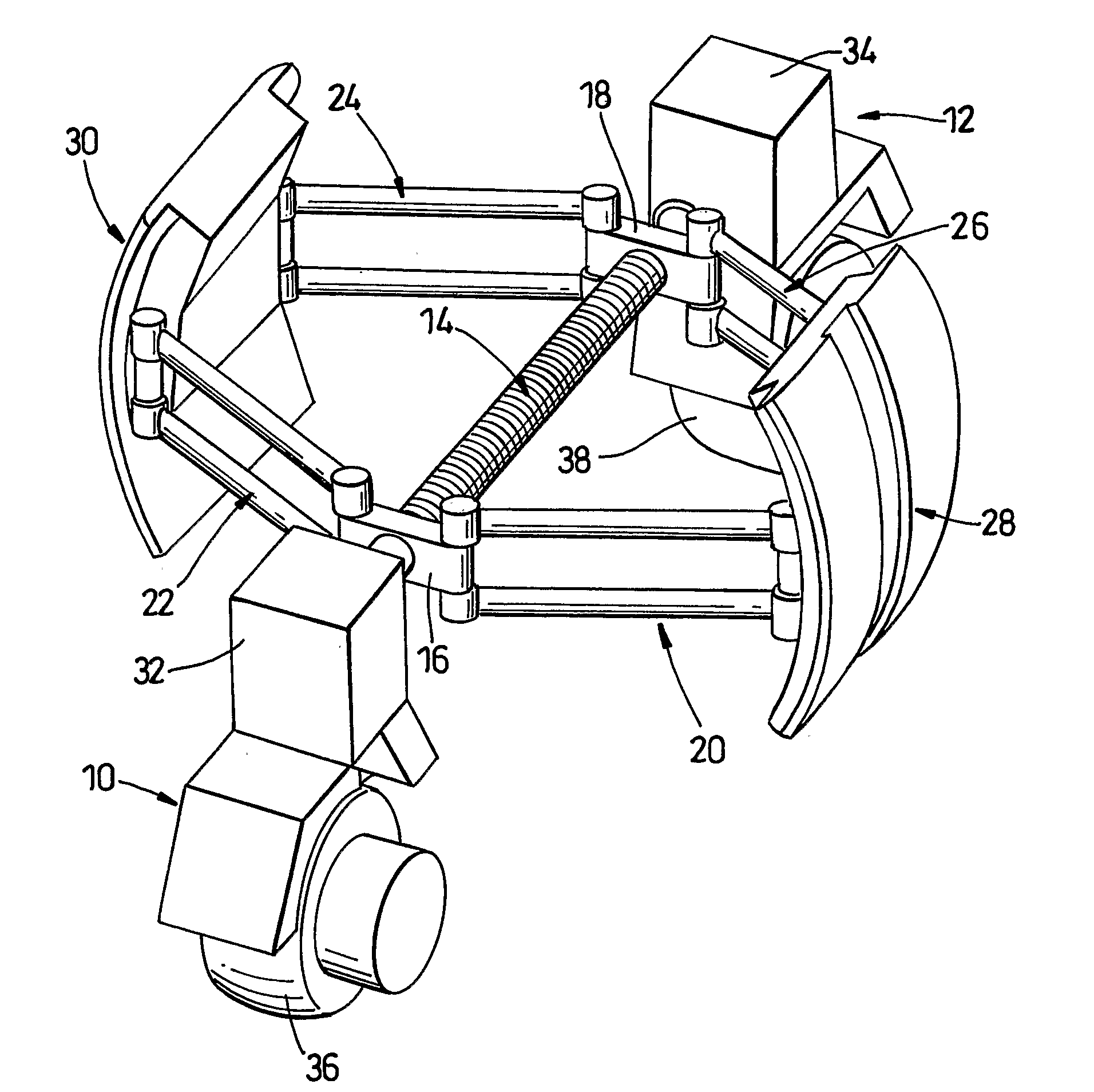
[0066]the present invention is illustrated in FIG. 1. In the embodiment of FIG. 1, a trolley unit is formed by first and second wheel units 10, 12 interconnected by a central spring 14. The spring 14 is such as to tend to pull the wheel units 10, 12 towards each other to a distance determined by the minimum extension of the spring. Each wheel unit 10, 12 has a bracket 16, 18 thereon, and each bracket 16, 18 has a pair of link arms 20 to 26 extending there from in opposite directions. A link arm 20, 26 from each bracket 16, 18 is connected to a first inspection platform 28, and the other link arms 22, 24 are connected to a second inspection platform 30. The connection of the link arms 20 to 26 to their respective brackets 16, 18 and inspection platforms 28, 30 are hinged to permit the angle of the link arms 20 to 26 relative to the spring 14 to be varied. Moreover, the link arms 20 to 26 or their mountings may be sprung loaded to provide a measure of compliance at dents and bends in ...

second embodiment

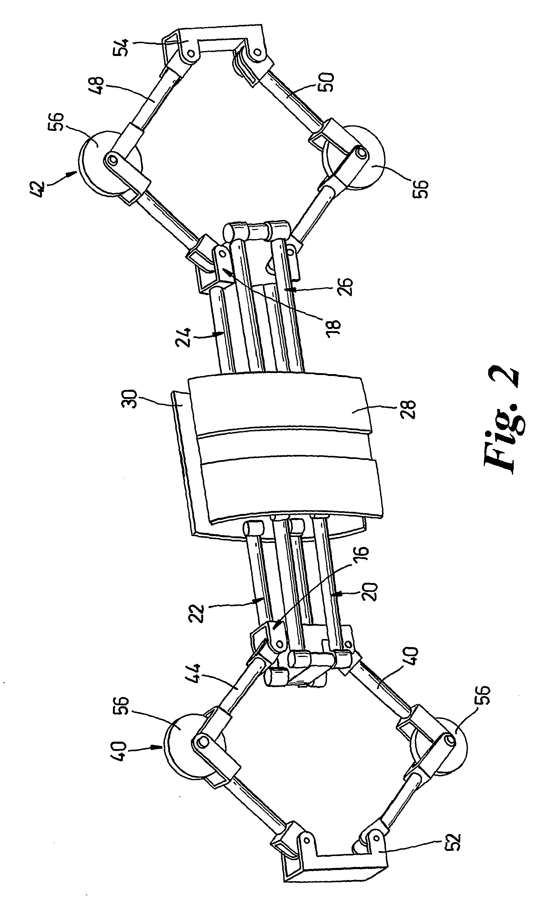
[0075]FIG. 3 illustrates the second embodiment, but with the platforms 28, 30 deployed. It can be seen that not only are the brackets 16, 18 are closer together, to deploy the inspection platforms 28, 30, but the bracket 52 is closer to the bracket 16, and the bracket 54 is closer to the bracket 18, thereby decreasing the angle between the arms of the V-shaped links 44 to 50 of the centralising units, moving the wheel 56 outwardly so that they maintain contact with the inner wall of the pipe.

[0076]Thus, the centralising units 40, 42 causes the central axis of the tool (along which the spring 14 runs) to be on the centre line of the pipe. This counters any sagging of the tool.

[0077]Preferably, the centralising units 40, 42 are pivotally connected to the brackets 16, 18 to permit the pivoting of centralising units 40, 42 about an axis parallel to the plane of the V-shaped links 44 to 50. This allows articulation of the tool, e.g. at bends in the pipe.

[0078]One disadvantage of the embo...

third embodiment

[0080]Thus, in the third embodiment illustrated in FIGS. 4 to 6 the trolley has a central rigid link 70, connected to the wheel units 10, 12 by articulated links 72, 74. Although the link arms 24 and 26 are connected to that central link by pivoting connections, the point of pivoting is fixed. The link arms 20, 22 are then connected at their ends remote from the inspection platforms 28, 30 to a block 76 which is slideably mounted in a slot 78 in the central link 70. The block 76 is connected to a worm screw extending within the central link 70 and driven by a motor 80.

[0081]FIG. 4 then illustrates the configuration of the tool in which the inspection platforms 28, 30 are fully deployed. The block 76 is at one end of the slot 78 closest to the motor 80, so that the spacing between that block 76 and the connection of the link arms 24, 26 to the central link 70 is as small as possible. FIG. 5 then illustrates a partially retracted position, in which the motor 80 drives the block 76 lef...


PUM


Abstract

An in-line pipe inspection tool has one or more inspection platforms (28, 30) which are connected to an elongate wheeled trolley by link arms (20 to 26). The trolley unit (10, 12) has drive means for driving the point of connection of the first link arm (20, 22) to the trolley (10) relative to the point of connection of the second link arm (24, 26) to the trolley (12), thereby to move the inspection platforms (28, 30) in a direction perpendicular to the direction of elongation of the trolley (10, 12). Thus the inspection platforms (28, 30) are movable which is relative to the trolley (10, 12) to permit the tool to be adapted to pipelines of different diameters. Moreover, the platforms (28, 30) preferably have permanent magnets which contain a rotatable magnet. The rotatable magnet permits the net magnetic field generated by the platform to be varied.

Description

BACKGROUND OF THE INVENTION[0001]1. Field of the Invention[0002]The present invention relates to an in-line pipe inspection tool, also known as a pipeline pig.[0003]2. Summary of the Prior Art[0004]It is known to inspect the inside of a pipeline using a pipeline pig which passes down the pipe. For magnetic inspection, the pig has permanent magnets defining first and second pole pieces, which are positioned adjacent the inner wall of the pipe. Those magnets then generate magnetic fields which magnetise the wall of the pipe. Sensors are provided between the magnetic poles, which detect the magnetic flux density at the internal surface of the pipe. The magnetic field in the pipe wall is normally constant, but is disturbed by a flux changing feature, such as a defect, weld bead or wall thickness change, and magnetic flux then leaks out of the pipe at such a feature, to be detected by the sensors. As the pipeline pig is driven along the pipe, the location of the pole pieces, and the sens...

Claims


Application Information

Patent Timeline
IPC IPC(8): F16L55/44G01M3/00G01M99/00F16L55/30
CPCF16L55/30G01N27/87F16L2101/30F16L55/44
Inventor GIBSON, MICHAELENVY, CHRISTOPHERMUNDELL, PAUL
Owner PII LIMITED
Why Eureka
Try Eureka