
Container cap

a technology for container caps and seals, applied in the field of container caps, can solve the problems of undetected solidification of adjuncts, and achieve the effect of superior sealing ability and easy cutting

Inactive Publication Date: 2008-04-24
CHO YOUNG KOOK
View PDF15 Cites 48 Cited by
  • Summary
  • Abstract
  • Description
  • Claims
  • Application Information

AI Technical Summary

Benefits of technology

"The present invention is a container cap with an openable sheet that can be easily cut through a band-shaped space defined between a weight member and an adjunct receiving part. The weight member and the openable sealing film are integrated with each other, preventing the sealing film from being cut to shreds and enhancing the reliability of the product. The openable sheet includes a weight member and an openable sealing film for sealing both the lower edge of the adjunct receiving part and the weight member. The technical effects of the invention are superior sealing ability and easy cutting of the openable sheet."

Problems solved by technology

In the case of techniques disclosed in Korean Patent Application Nos. 10-2003-023243 and 10-2004-002154, there is inconvenience in which, after a band is removed, a cap is rotated in a clockwise direction to discharge an adjunct and is thereafter rotated in a counterclockwise direction to open a container.
Furthermore, there is a problem in that the adjunct can undesirably solidify due to the permeation of moisture, gas pressure or physical action.
However, in the conventional container cap described above, because an edge part of the openable film is relatively thin, and because a method, in which the thin edge part of the openable film is cut by rotation of the cutting blade of the operational cap member to add the adjunct into the contents, is used, there is the possibility of the permeation of air or moisture, which dries or wets the adjunct and thus spoils it, through the thin edge part of the openable film.

Method used


Image

  • Container cap
  • Container cap
  • Container cap

Examples

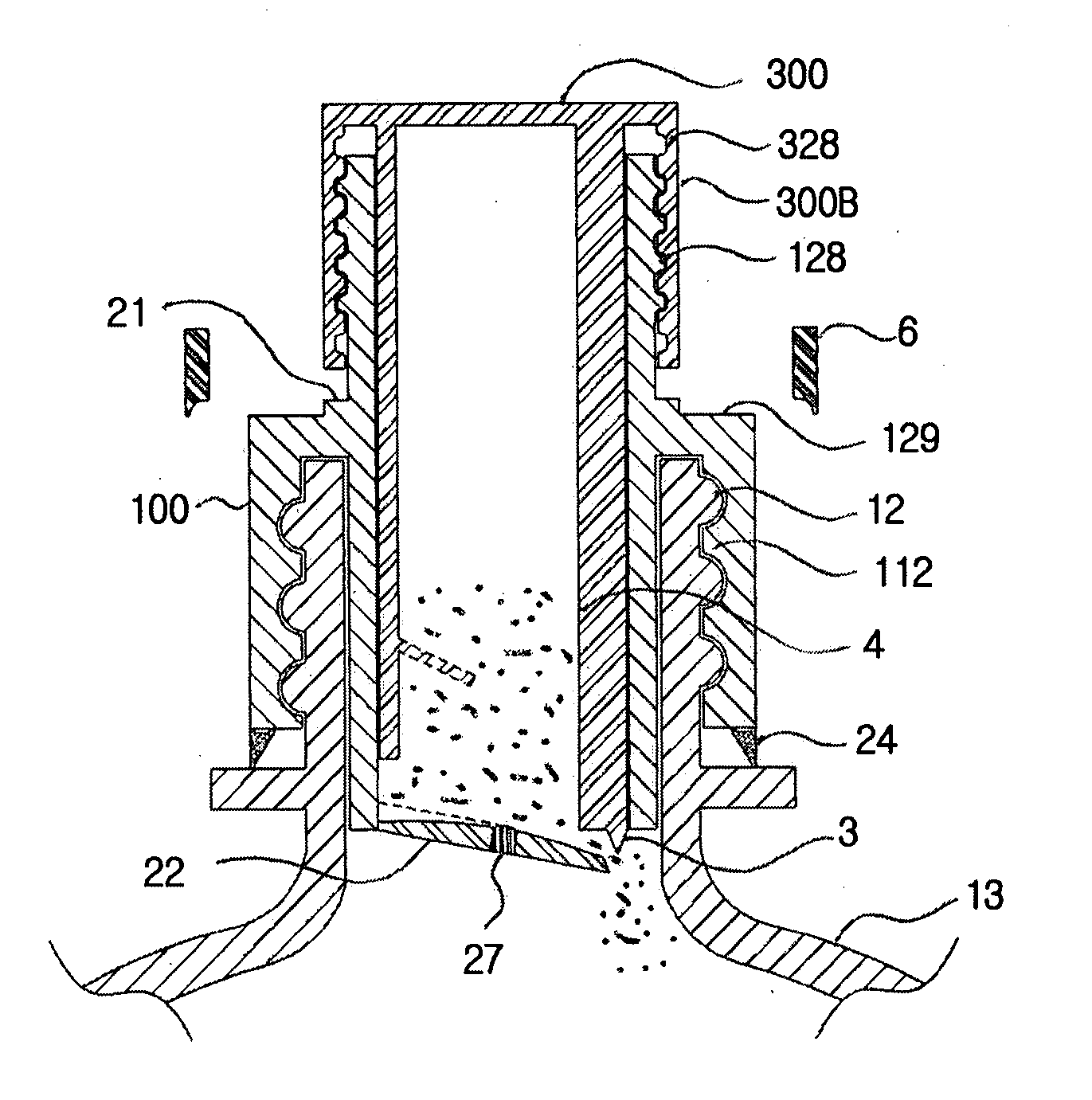
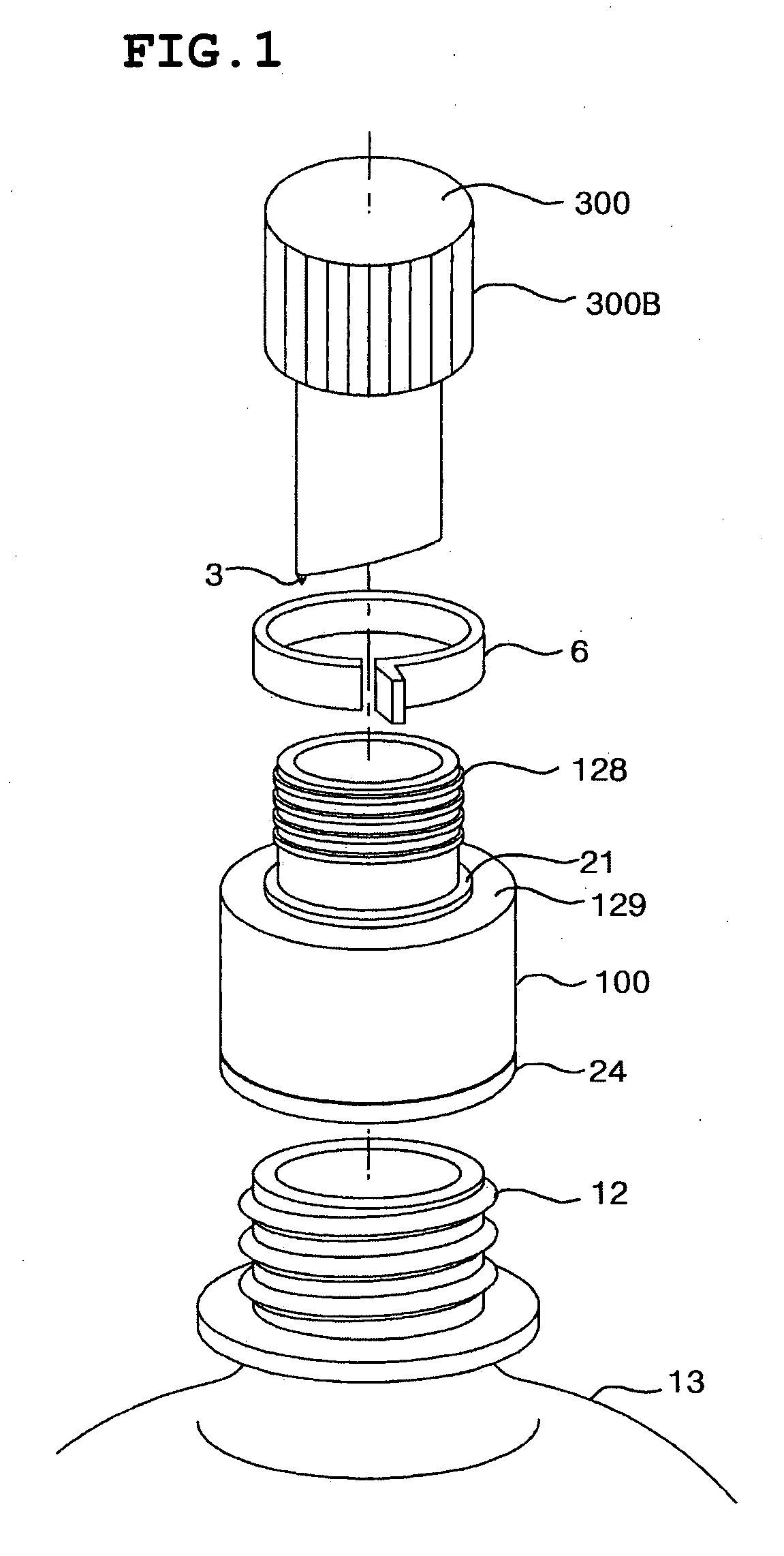
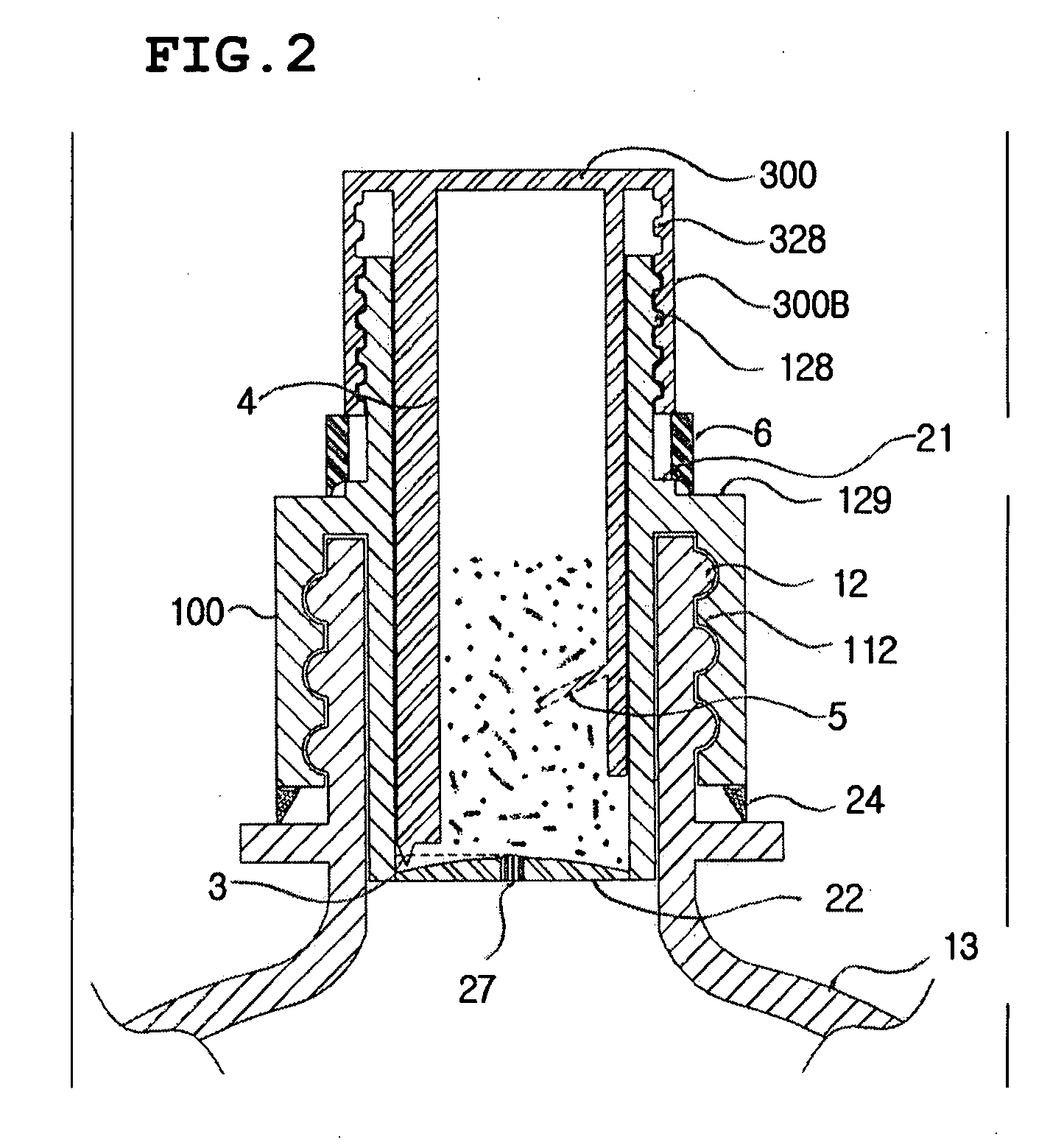

Embodiment Construction

[0027]Hereinafter, a preferred embodiment of the present invention will be described in detail with reference to the attached drawings.

[0028]FIG. 5 is a sectional view illustrating a container cap according to the preferred embodiment of the present invention. FIG. 6 is a sectional view of a critical part of the container cap of the present invention.

[0029]As shown in the drawings, the container cap of the present invention includes a base cap member 100, which is coupled to an opening of a container, an operational cap member 300, which is coupled to the upper end of the base cap member 100 and a cutting blade 3, and an openable sheet, which is the bottom of an adjunct receiving part 77-3. The openable sheet includes a weight member 77, which has a diameter less than that of an arc part, along which the bottom of the adjunct receiving part 77-3 is cut, at least one connection rib 77-2, which connects the weight member 77 to the lower edge of the adjunct receiving part 77-3, and an ...


PUM


Abstract

Disclosed herein is a container cap allowing the addition of an adjunct. The container cap includes a base cap member, which is a lower cap body coupled to a neck part of a container, an operational cap member, which is an upper cap body coupled to the upper end of the base cap member, and an openable sheet, which is provided on the lower end of one selected from the base cap member and the operational cap member. The openable sheet is able to be cut to discharge the adjunct. The container cap further includes a cutting means for cutting the openable sheet. The cutting means is provided in a remaining one selected from the base cap member and the operational cap member at a position corresponding to the openable sheet. The openable sheet includes a weight member, which has a diameter less than a diameter of an arc part of the openable sheet to be cut. A connection rib is connected between the weight member and a lower edge of an adjunct receiving part of the base cap member. The openable sheet further includes an openable sealing film, which seals both the lower edge of the adjunct receiving part and the weight member.

Description

BACKGROUND OF THE INVENTION[0001]1. Field of the Invention[0002]The present invention relates generally to container caps allowing the addition of adjuncts and, more particularly, to a container cap, which includes a base cap member, which is coupled to an opening of a container and has an adjunct receiving part, an operational cap member, which is coupled to the upper end of the base cap member, and an openable sheet, which is the bottom of the adjunct receiving part and comprises a weight member having a diameter less than that of the adjunct receiving part and an openable sealing film attached to the lower surface of the weight member and to the open lower end of the adjunct receiving part.[0003]2. Description of the Related Art[0004]In the case of techniques disclosed in Korean Patent Application Nos. 10-2003-023243 and 10-2004-002154, there is inconvenience in which, after a band is removed, a cap is rotated in a clockwise direction to discharge an adjunct and is thereafter rot...

Claims


Application Information

Patent Timeline
Patent Type & Authority Applications(United States)
IPC IPC(8): B65D51/28B65D25/08B65D81/32
CPCB65D2101/0038B65D51/285B65D2401/25B65D25/08B65D51/28B65D81/32
Inventor CHO, YOUNG KOOK
Owner CHO YOUNG KOOK
Learn More