Sterilizing Device And A Method For Sterilizing Of Fluids

a technology of a sterilizing device and a fluid, which is applied in the direction of measuring apparatus housings, water/sludge/sewage treatment, specific water treatment objectives, etc., can solve the problems of reducing functionality or safety, operating costs, etc., and achieve the effect of increasing the sterilization effect of uv waves

Inactive Publication Date: 2008-04-24
KOHLER CO
View PDF15 Cites 82 Cited by
  • Summary
  • Abstract
  • Description
  • Claims
  • Application Information

AI Technical Summary

Benefits of technology

[0012] A further problem to be solved is the save substitution of expensive UV-lamps by the implementation of lower cost UV-lamps such that operating costs can be reduced without reduction of functionality or safety.
[0043] According to a preferred option, the fluid to be treated may furthermore be submitted to power ultrasonic waves for providing a cavitation effect in the fluid for destroying contaminants like bacteria and / or various microbes and / or plancton.

Problems solved by technology

A further problem to be solved is the save substitution of expensive UV-lamps by the implementation of lower cost UV-lamps such that operating costs can be reduced without reduction of functionality or safety.
A further problem to be solved is to provide a device easily adoptable to different demands.
A still further problem to be solved is to provide a device which is not committed to a single type of UV-lamp.

Method used


Image

  • Sterilizing Device And A Method For Sterilizing Of Fluids
  • Sterilizing Device And A Method For Sterilizing Of Fluids
  • Sterilizing Device And A Method For Sterilizing Of Fluids

Examples


first embodiment

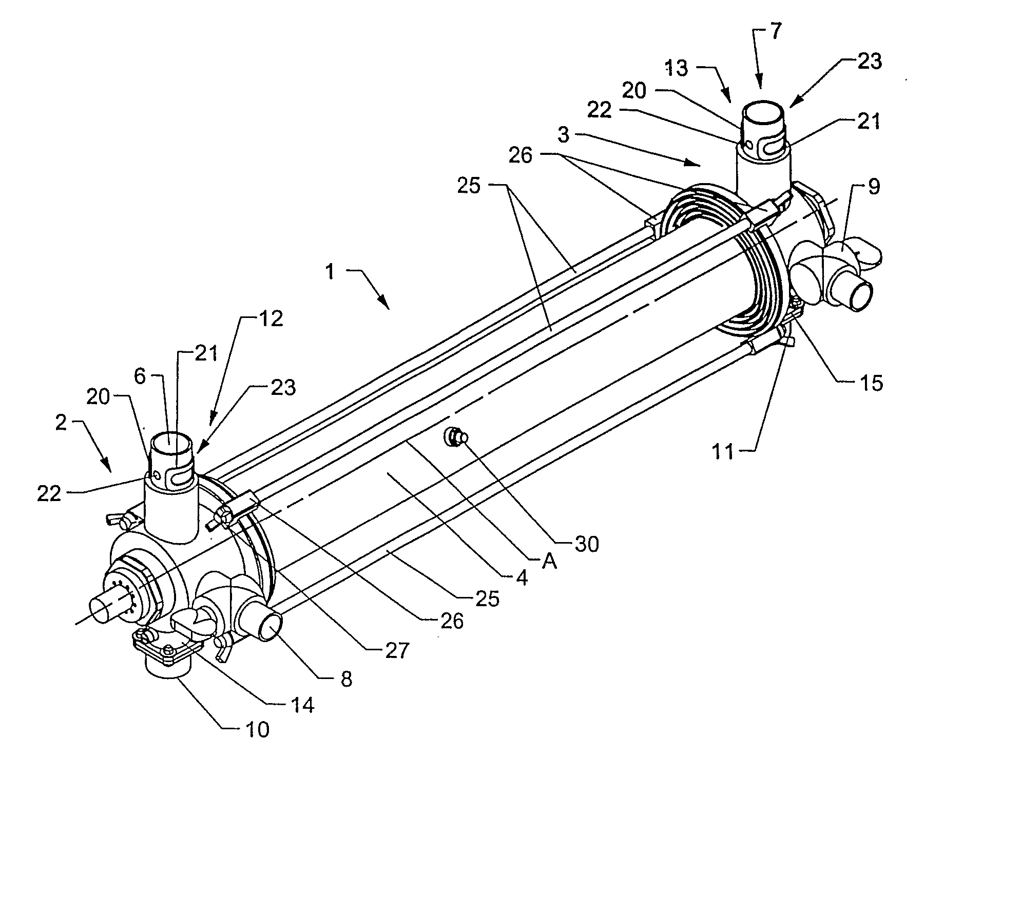
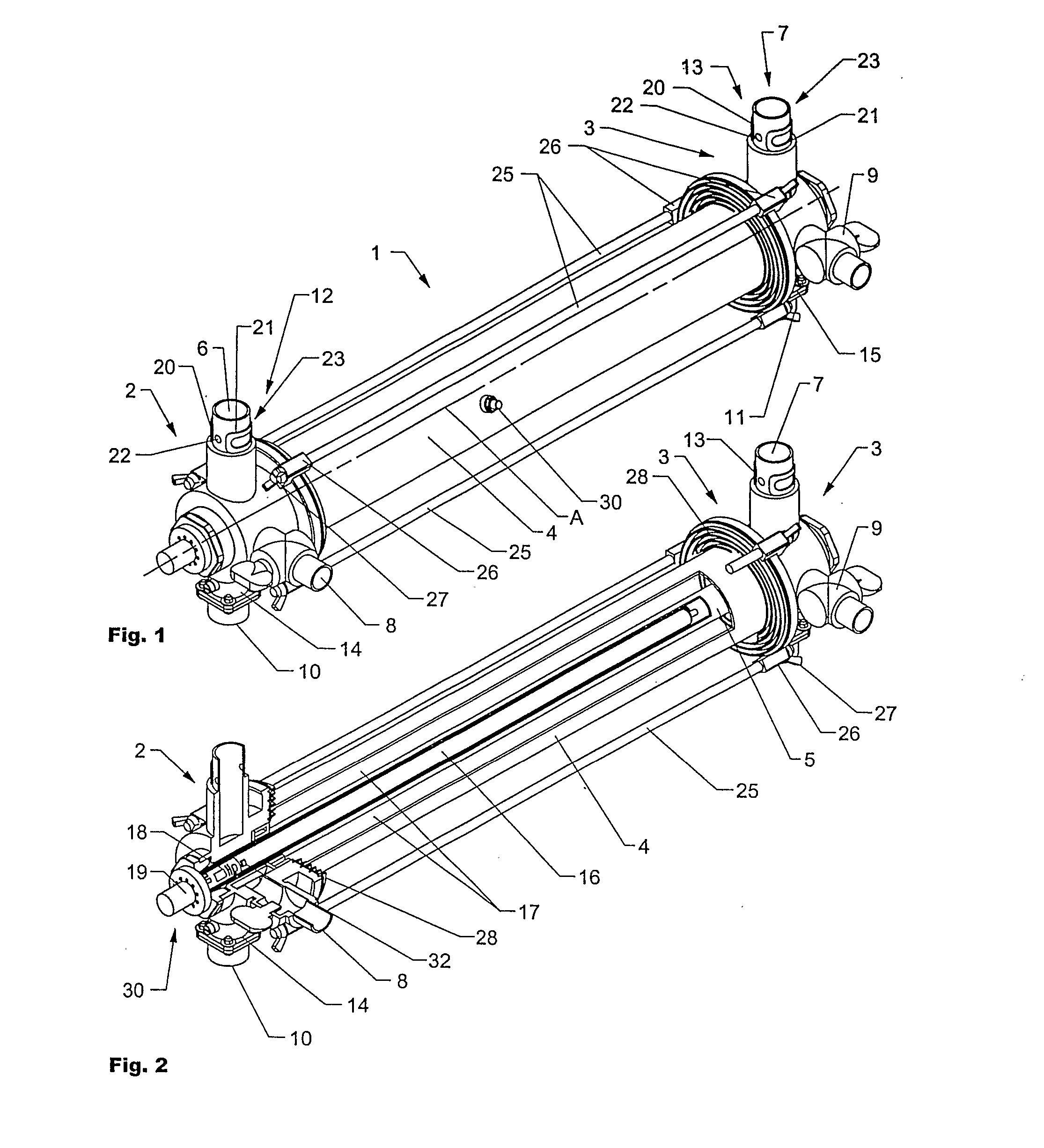
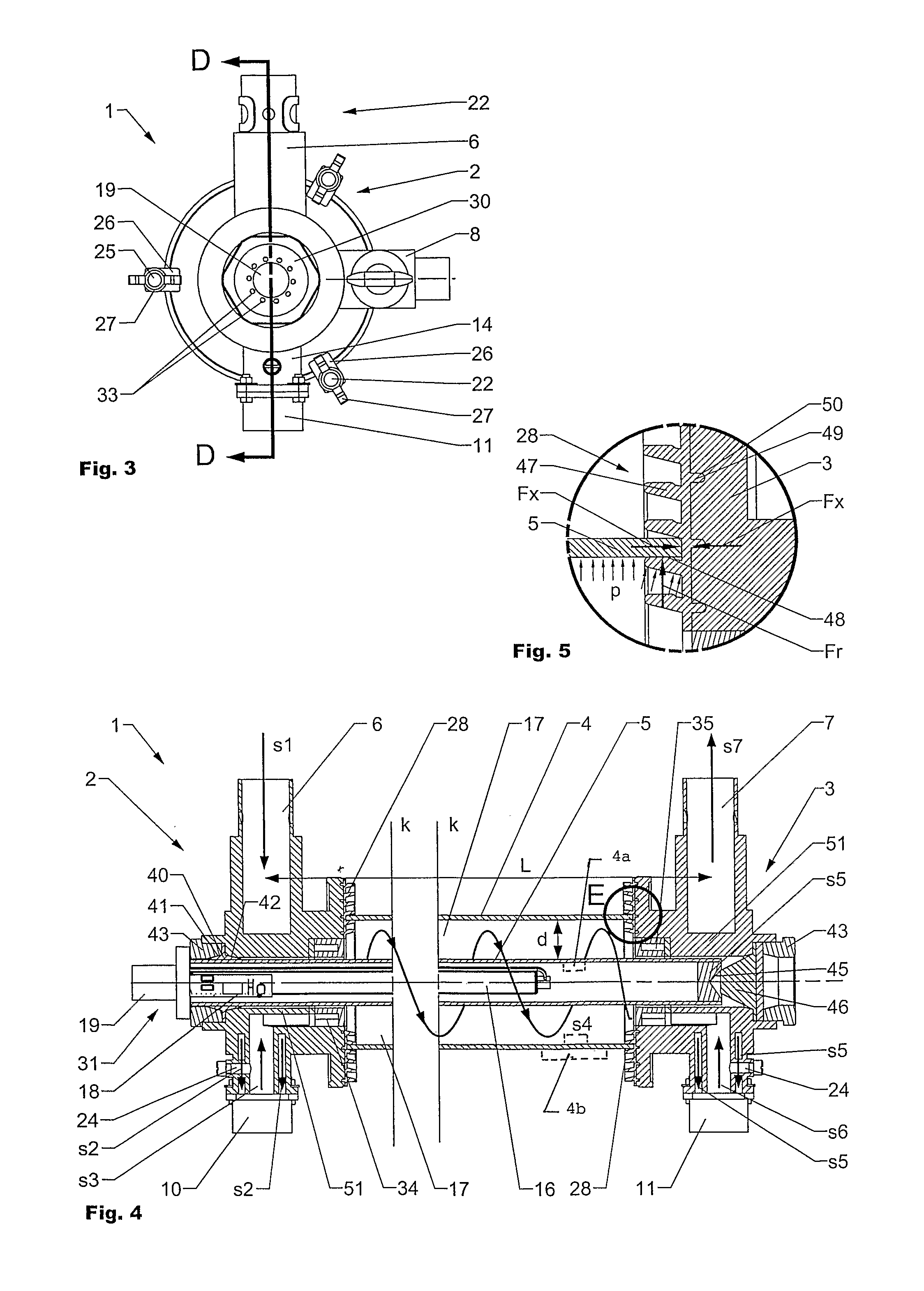
[0085]FIG. 6 shows schematically a typical flow path s through a sterilizing device 1 according to the present invention. The sterilizing device 1 is not shown in full detail to avoid masking of the flow path s. The first and the second flange 2, 3, the vortex unit 34 and the conveyer unit 35 are shown in a disassembled way, due to the reason that they are important for the guidance of the flow path s. Corresponding sections of the flow path s are drawn on top of each other. A front section of the first flange 2 is cut away offering a view on the inside of the first flange 2 and the first interface flange 14. The sterilizing device is normally connected to adjacent pipes or other units such as pumps or filters. These units are not shown in detail in the present drawing. When the valve gate units mounted on the first and the second interface flange 14, 15 are open the fluid enters the first flange 2 through the first main connection piece 6 and if fitted a flow measuring device (not ...

second embodiment

[0091]FIG. 9 is showing the sterilizing device 1 in a perspective view. A part of the device is cut away such that it is possible to view the inside. Between the first and the second flange 2, 3 the outer tube 4 is arranged. Four tie rods 25 are connecting the first and the second flange 2, 3 clamping the outer tube 4 in between. The first and the second flange of the present embodiment are having a symmetrical setup with central opening 70 wherein the inner tube 5, which is made of a UV-transparent material, is clamped by a coupling nut 43 and a second gasket 40 on each side. The inner tube 5 is suitable to receive a lamp unit (not shown in detail) as shown in FIG. 8 having one or more UV-lamps. The shown embodiment offers the advantage of straight-through ventilation of the lamp unit by a ventilation unit (not shown in detail), such that the lamp may be cooled and / or heated to guarantee best performance of sterilizing. Depending on the type of UV-lamp best performance is obtained ...

third embodiment

[0094]FIG. 11 shows a sterilizing device 1 and FIG. 12 shows the sterilizing device according to FIG. 11 partially cut offering a view at the inside. This embodiment is suitable to be used for water storage, e.g. in stationary water tanks, tanker trucks or water bags. The sterilizing device 1 is inserted e.g. into a filling hole of a tank resting on the rim of the filling hole (not shown in detail), whereby the intake and outlets 80, 81 of the sterilizing device 1 are immersed into the liquid. The fluid pumped into the tank by passing through the second main connection 6 and drained by the first main connection piece 7. In both cases the fluid passes through the first and the second flanges 2, 3 in general according to the flow paths as described in accordance with FIG. 6.

[0095] As it can be seen the interface flange 15 of the second flange 3 is equipped with a filter unit 86 through which the fluid passes while being drained. The amount of volume is measured by flow measuring devic...


PUM

PropertyMeasurementUnit
angleaaaaaaaaaa
angleaaaaaaaaaa
velocityaaaaaaaaaa

Abstract

The invention is directed to an improved sterilizing device (1) for sterilizing of a fluid by UV-radiation. The sterilizing device (1) has a modular setup with at least one flange (2, 3), an inner and an outer tube (4, 5) and comprises at least one UV-lamp (16) for emitting UV-radiation. A lamp tag (32) attached to or incorporated in the at least one UV-lamp (16) comprises information regarding the UV-lamp (16). The lamp tag (32) is interconnected with a lamp sensor unit (18) and / or a control unit (19) and may comprise sensors to control the sterilizing process.

Description

TECHNICAL FIELD [0001] The invention concerns a sterilizing device for sterilizing of a fluid by UV-radiation comprising at least one UV-lamp for emitting UV-radiation, a lamp tag attached to or incorporated in the at least one UV-lamp comprising information regarding the UV-lamp. [0002] The invention concerns also a sterilizing method for sterilizing of a fluid by UV-radiation comprising at least one UV-lamp for emitting UV-radiation, a lamp tag attached to or incorporated in the at least one UV-lamp comprising information regarding the UV-lamp. BACKGROUND ART [0003] From the prior art it is known that fluids such as water or air can be sterilized by ultraviolet (UV) radiation. The fluid to be sterilized is therefore exposed to a source of UV radiation for a specific time. [0004] CH 477 825 shows a device for sterilizing a fluid by UV radiation. The fluid is exposed to UV radiation in a gap between an inner and an outer tube which are arranged concentrically to each other. In the g...

Claims


Application Information

Patent Timeline
Patent Type & Authority Applications(United States)
IPC IPC(8): A61L2/025A61L2/10B06B1/00G01N37/00A61L9/20C02F1/32C02F1/36
CPCA61L9/20C02F1/325C02F1/36C02F1/487C02F2201/326C02F2303/04C02F2201/3227Y02W10/37A61L2/10
Inventor KOHLER
Owner KOHLER CO
Why Eureka
Try Eureka