
Low NOx staged fuel injection burner for creating plug flow

a burner and plug flow technology, applied in the field of staged burners, can solve the problems of large decrease in tube life, adversely affecting the economics of the plant, and affecting the efficiency of the plan

Inactive Publication Date: 2008-04-24
AIR PROD & CHEM INC
View PDF29 Cites 35 Cited by
  • Summary
  • Abstract
  • Description
  • Claims
  • Application Information

AI Technical Summary

Benefits of technology

[0005]The subject invention constitutes a staged fuel burner for establishing a plug-like flow, and is particularly useful in furnaces, such as ethylene crackers, reformers, etc. The staged burner comprises a central nozzle and plural staged nozzles. The central nozzle has an orifice producing a jet of air directed along a central longitudinal axis. The staged nozzles surround the central nozzle and each has at least one orifice producing a s

Problems solved by technology

As is known, operating a reformer tube above the desired temperature can cause large decreases in tube life.
This, in turn will adversely affect the economics of the plant since the tubes are a substantial portion of the overall cost of the plant and require large expenditures of time and effort to replace one that has failed.
Tube hot spots can arise from undesirable furnace flow patterns which cause flame impingement.
NOx emissions have been identified as contributing to the degradation of environment, particularly degradation of air quality, formation of smog and acid rain.

Method used


Image

  • Low NOx staged fuel injection burner for creating plug flow
  • Low NOx staged fuel injection burner for creating plug flow
  • Low NOx staged fuel injection burner for creating plug flow

Examples


Embodiment Construction

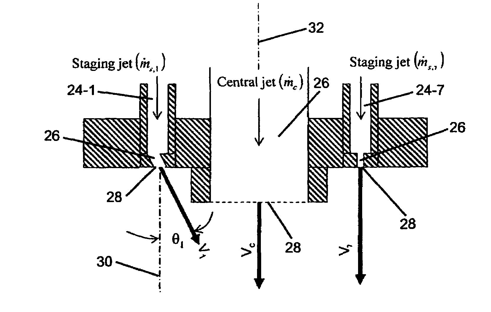
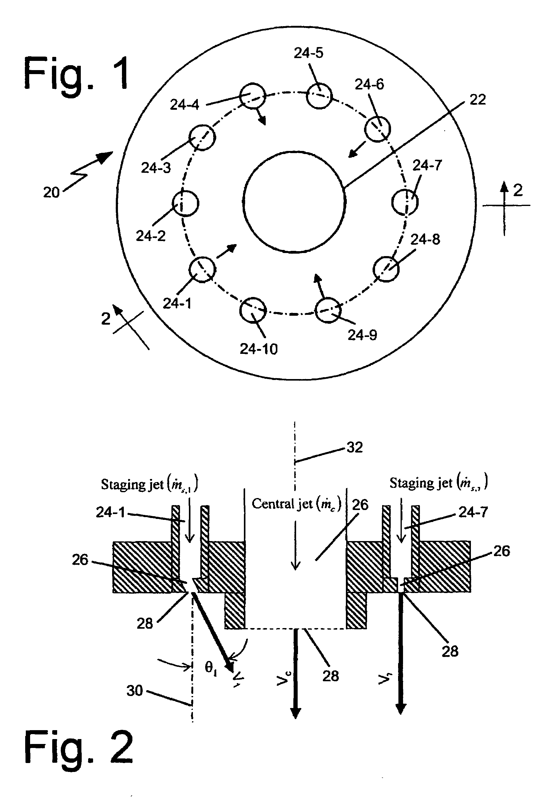
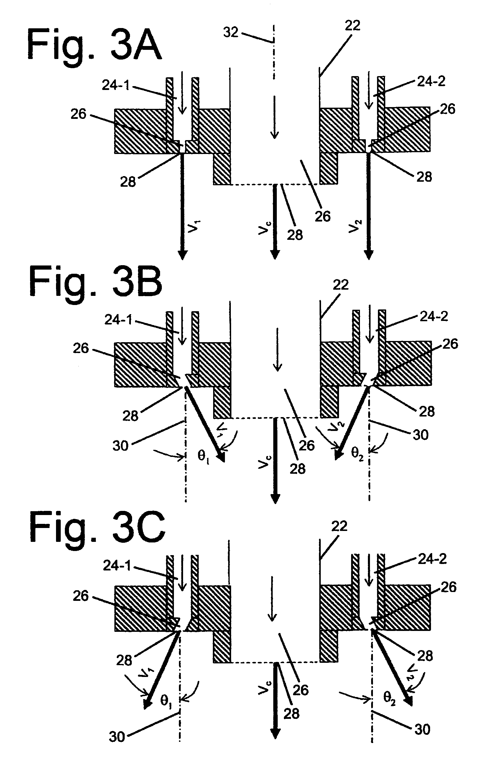
[0025]Referring now to FIG. 1 wherein like reference characters refer to like parts there is shown at 20 one exemplary embodiment of a staged fuel burner constructed in accordance with this invention. That burner exhibits good plug flow characteristics and low NOx emissions and is what is commonly referred to as a staged burner. To that end, the burner 20 includes a central nozzle 22 that is surrounded by a plurality of staging or staged nozzles 24. In the exemplary embodiment of FIG. 1 ten such staged nozzles 24-1 to 24-10 are provided. That arrangement is exemplary of a multitude of burners that can be constructed in accordance with this invention. In particular, burners constructed in accordance with this invention can include any number of staged nozzles surrounding the central nozzle. Each nozzle may include a single orifice or plural orifices. Moreover, the orifices may be of any shape and size, as will be seen later with reference to FIGS. 8A-8D and 9A-9I. In the exemplary em...


PUM


Abstract

A burner for producing a plug-like flow and low NOx emissions. The burner has a central air jet and plural staged fuel jets surrounding the central jet. The ratio of the sum of the momentums of vector components of the staged jets along respective axes parallel to the central longitudinal axis of the central jet to the momentum of the central jet along that axis is within the range of 0.5 to 1.5 and most preferably 0.8.

Description

BACKGROUND OF THE INVENTION[0001]The present invention relates to burners for furnaces, and in particular to staged burners for creating a plug-type flow pattern with low nitrogen oxides (NOx) emissions.[0002]Furnaces for ethylene cracking and other industrial processes, e.g., steam-methane reformers, typically make use of burners utilizing fuels such as natural gas, propane, hydrogen, refinery off-gas and other fuel gas combinations of various calorific values. For example, steam-methane reformer furnaces are used to produce hydrogen and carbon monoxide by reforming a hydrocarbon feed with steam and, at times, carbon dioxide at high temperatures. The furnace used for steam-methane reforming can be configured in several different structures. One of the most conventionally used arrangements for such reformer furnaces has vertical reformer tubes arranged in rows. The burners of the furnace can be located on the furnace's floor, its ceiling or its walls. As is known, operating a reform...

Claims


Application Information

Patent Timeline
IPC IPC(8): F23C7/00
CPCF23C6/045F23C2201/20F23C2900/06043F23D2900/14003F23D14/48F23D14/58F23D23/00F23D14/22
Inventor LI, XIANMING JIMMYJOSHI, MAHENDRA LADHARAMSLAVEJKOV, ALEKSANDAR GEORGI
Owner AIR PROD & CHEM INC
Learn More