
Ceramic Reinforcement Bars For Direct Dental Bridge

a technology of cement reinforcement bars and direct dental bridges, which is applied in the field of cement reinforcement bars for direct dental bridges, can solve the problems of not being easy to perform, not being easy to place, and not being easy to bond well to dental filling materials and dental bonding resins, so as to facilitate the dentist's understanding of how, facilitate the placement of reinforcement bars, and facilitate the dentist's job. the effect of easy operation

Inactive Publication Date: 2008-04-24
MORRIS CHRISTOPHER
View PDF5 Cites 9 Cited by
  • Summary
  • Abstract
  • Description
  • Claims
  • Application Information

AI Technical Summary

Benefits of technology

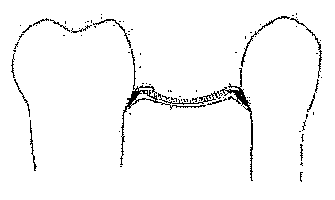
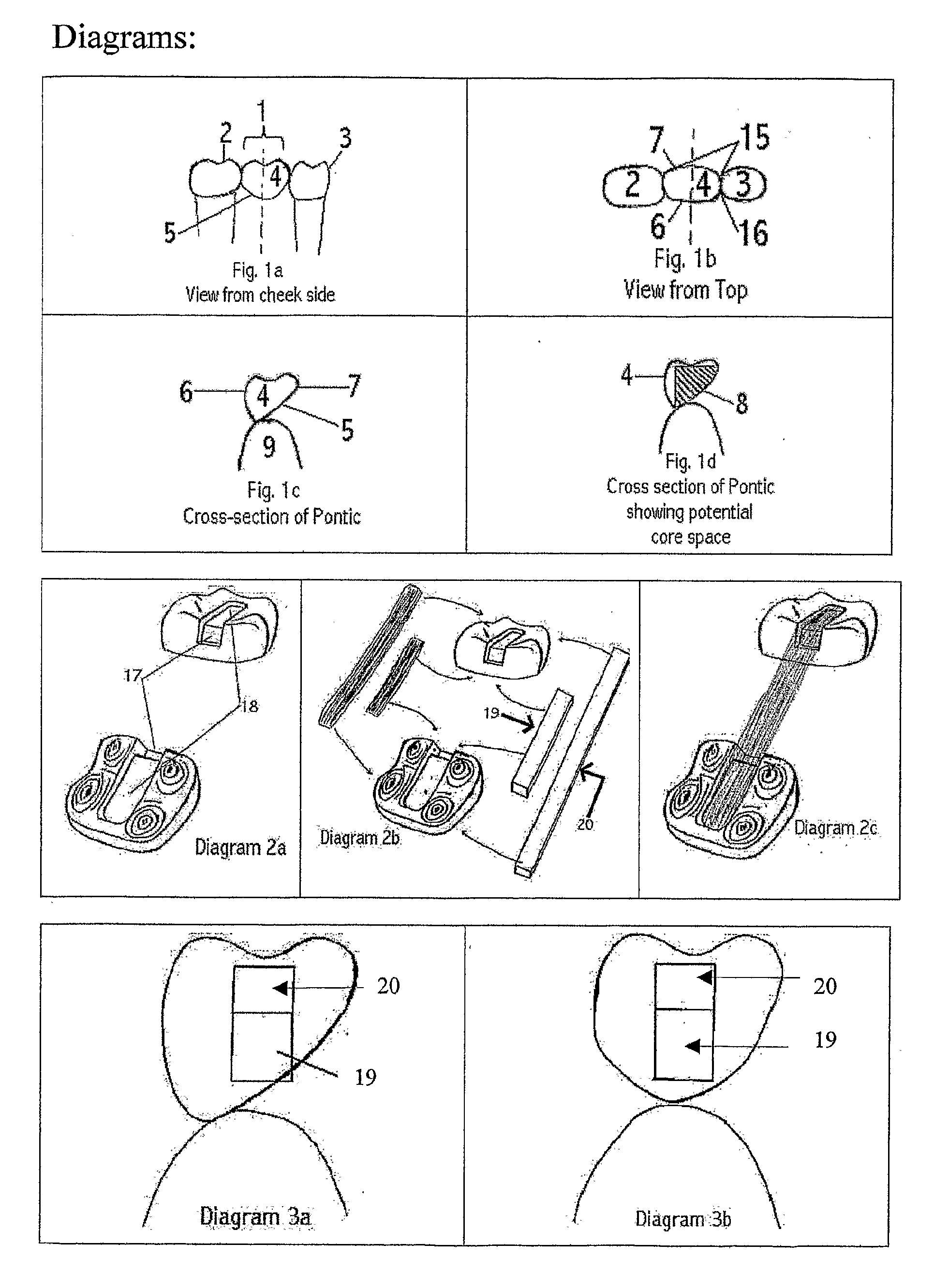
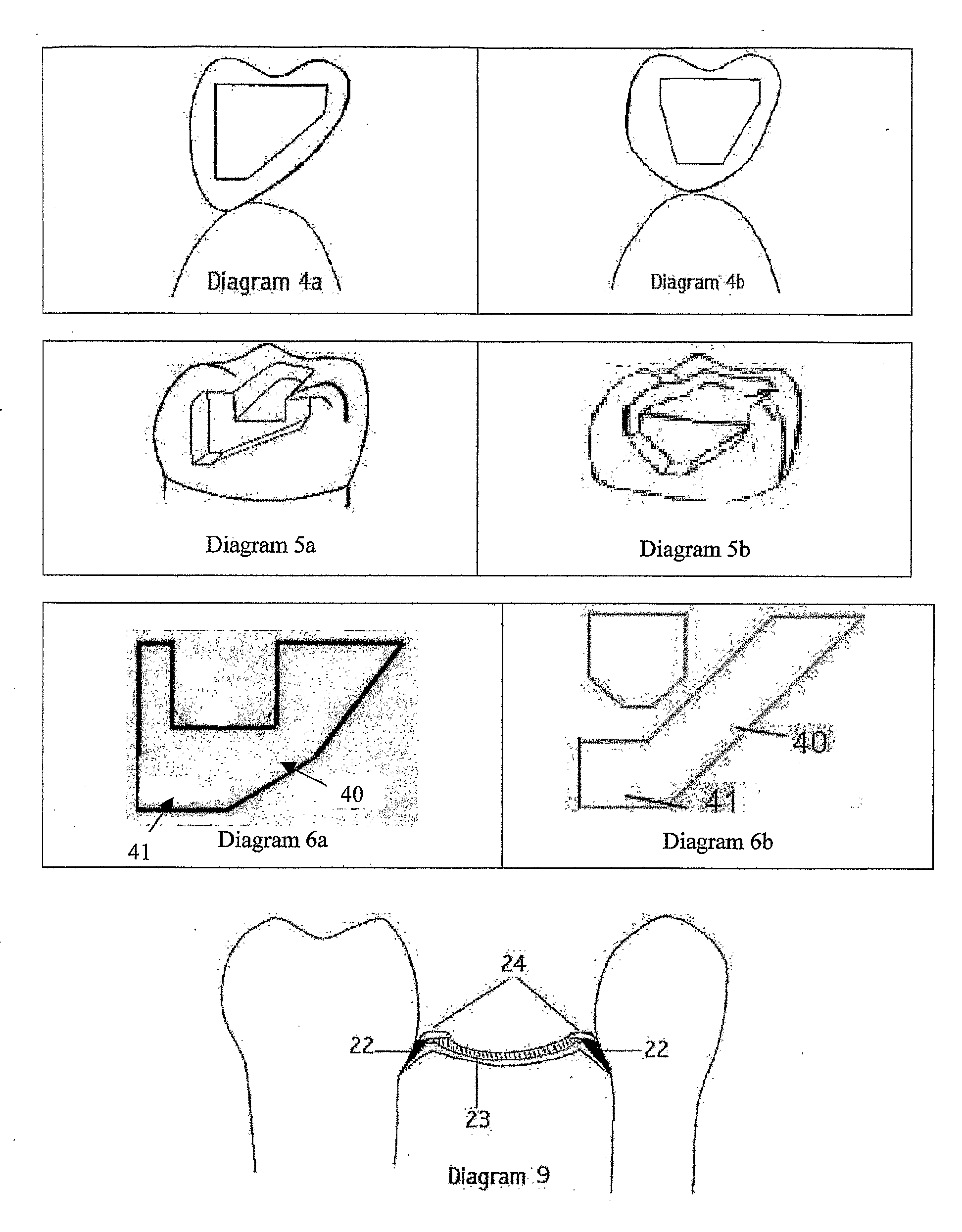
"The invention aims to make a strong direct bridge that can resist high occlusal forces, while also being easy to place and cost-effective for patients. The invention also aims to protect the proximal gingival abutment surface from decay using a dental material wedge to cover this surface. The invention includes a new cavity design that maximizes the use of the cross-sectional area of the pontic as spanning reinforcement material, resulting in a stronger and more efficient bridge. The invention also includes a reinforcement design that takes advantage of the cross-sectional shape of the pontic to direct the forces of occlusion around the center of rotation of the abutment tooth. Overall, the invention improves the strength of the bridge, simplifies the placement process, and reduces the time and cost for patients."

Problems solved by technology

The disadvantages of the above claims are that although metal is strong, it does not bond well to dental filling materials and dental bonding resins.
Although this U.S. Pat. No. 6,039,569 describes their technique as being easy, it is not easy to perform in the mouth as it is dark, difficult to see, as the lips, cheek and tongue are in the way, and saliva is continuously egressing onto the abutment teeth wetting and contaminating the surfaces of the abutment cavities and the reinforcement as it is being assembled and the pontic as it is being built.
This is difficult and time consuming.
The effort required to create this pontic is significant because while he is working, blood and saliva are constantly egressing onto the teeth that he is trying to keep dry as he works.
So placement of the direct placement bridge is a very difficult battle, not only to create the pontic but to keep the teeth dry while the work is being accomplished.
The next reason that direct bridges are not being used by dentists very often is that they are presently not very strong and therefore are not relied upon by dentists to provide bridges where the dentist believes that there will be any reasonably strong biting forces being applied to the direct bridge.
In other words, to my knowledge no one has actually studied the issue of how to provide a strong direct bridge directly in the mouth, and therefore there are no protocols or guidelines established for dentists so that they know how to create a strong direct placement bridge.
In addition there are no tools or materials available to assist the dentist in making a direct bridge.
They are also used to make prosthetic hips and are therefore biocompatible.

Method used


Image

  • Ceramic Reinforcement Bars For Direct Dental Bridge
  • Ceramic Reinforcement Bars For Direct Dental Bridge
  • Ceramic Reinforcement Bars For Direct Dental Bridge

Examples


Embodiment Construction

[0125] The effort so far has been to try to find a way to reinforce a direct bridge that is placed directly in the mouth without assistance from a laboratory. However, the same principles that have been used in my direct bridge placement can also be used for a laboratory-processed bridge. An embodiment of my invention for the laboratory-processed bridge would be to use the reinforcement structures of Zirconia or Alumina or a combination of both for a laboratory processed bridge.

[0126] Examples of the laboratory-processed bridge can be seen in Diagrams 24a-24d.

[0127] Diagram 24a shows a pontic with a rectangular zirconia bar through the middle of the pontic and the proximal ends of zirconia bar cemented into a cavity preparation in the mesial distal of the abutment teeth. Possible cross sections of this bar can be seen in 24c and 24d; however numerous cross-section designs to aid in retention of the pontic could be manufactured.

[0128] Diagram 24b shows either two possibilities whe...


PUM

PropertyMeasurementUnit
widthaaaaaaaaaa
widthaaaaaaaaaa
diameteraaaaaaaaaa

Abstract

A direct dental bridge, built in the mouth of a patient, comprising Zirconium oxide or Aluminium oxide reinforcement bars (19, 20) onto which the pontic of the bridge is assembled. The ceramic bars of the present direct dental bridge bond better to dental filling materials and dental bonding resins than metal bars, and are easier to use than fiber ribbons and resin bars. Also disclosed is a method of building a direct dental bridge further comprising the use of a dental material gingival wedge bonded on an abutment tooth, demale molds for surface veneers, malleable gingival veneers and occlusal / buccal surface veneers.

Description

[0001] The invention includes new techniques, materials, and methods to build a bridge placed directly in the mouth of the patient without the laboratory making the bridge. BACKGROUND OF THE INVENTION [0002] If a single tooth, or sometimes two adjacent teeth are lost, and there are healthy teeth on either side of the space created by the lost teeth, then a fixed dental prosthesis called a bridge can be used to replace the one or two teeth by fixing the prosthesis to the healthy teeth and placing a span containing replacement teeth between the healthy teeth. [0003] Bridges can be indirect or direct bridges. The dentist himself makes a direct bridge right in the mouth of the patient. [0004] An indirect bridge is fabricated in a laboratory on a model of the patient's teeth. Once the indirect bridge is made in the laboratory, it is sent back to the dental office where the dentist cements it in place in the patient's mouth. [0005] In order to understand a bridge and the terminology in th...

Claims


Application Information

Patent Timeline
Patent Type & Authority Applications(United States)
IPC IPC(8): A61C13/003A61C3/00A61C5/77A61C13/275A61K6/027
CPCA61C5/10A61K6/024A61C13/275A61C5/77A61K6/818
Inventor MORRIS, CHRISTOPHER
Owner MORRIS CHRISTOPHER
Learn More