Tapered roller bearing and differential gear apparatus

a technology of differential gear and roller bearing, which is applied in the direction of bearing cooling, gearing, gear details, etc., can solve the problems of increasing the amount of consumed energy, reducing the transmission efficiency, and worsening the fuel consumption of the vehicle, so as to achieve excellent durability, low cost, and low fuel consumption

Inactive Publication Date: 2008-04-24
JTEKT CORP
View PDF6 Cites 25 Cited by
  • Summary
  • Abstract
  • Description
  • Claims
  • Application Information

AI Technical Summary

Benefits of technology

[0032] The differential gear apparatus of the above construction, when mounted on a vehicle, contributes to low fuel consumption, and is excellent in durability, and can be provided at a low cost. Furthermore, the inner diameter of the annular member is larger than the outer diameter of the larger rib portion of the inner ring, and therefore the outer peripheral portion of the annular member is fixed to the inner peripheral portion of the outer ring, and in this condition the inner ring can be inserted from the back side toward the front side, and can be mounted and fixe

Problems solved by technology

As a result, the torque of the bearings increases, so that the transmission efficiency is lowered, and therefore the amount of consumed energy increases, and the fuel consumption of the vehicle is worsened.
And besides, when the amount of supply of the lubricating oil L increases, the amount of foreign matters flowed into (included in) the bearings increases, and wear and damage of the tapered roller bearings 110 and 112 are accelerated, and therefore there is a fear that the life of the bearings may be shortened.
(2) On the other hand, when the amount of supply of the lubricating oil L is restricted in an attempt to improve the fuel consumption of the vehicle, there is a fear that seizure may occur because of lack of lubrication.
As a result, the amount of supply of the lubricating oil L to a larger rib portion 111b of the inner r

Method used


Image

  • Tapered roller bearing and differential gear apparatus
  • Tapered roller bearing and differential gear apparatus
  • Tapered roller bearing and differential gear apparatus

Examples


first embodiment

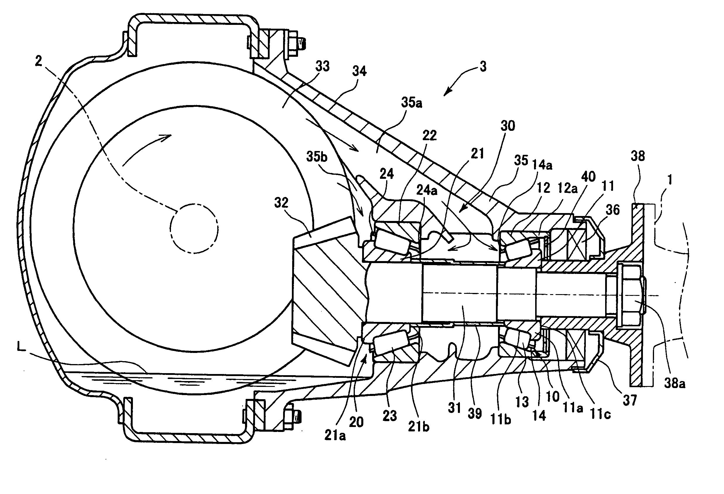
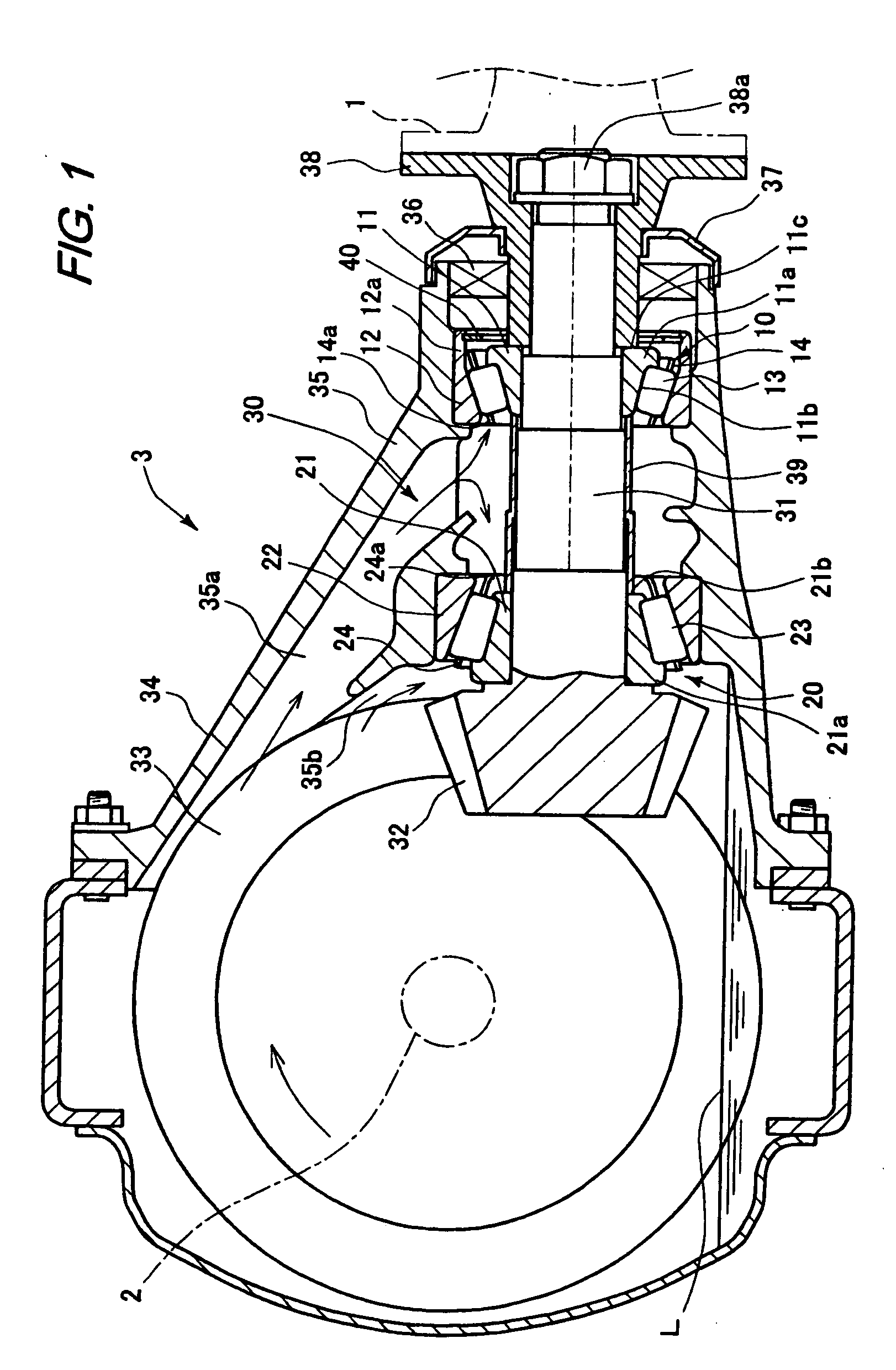
[0041] A preferred embodiment of the present invention will now be described with reference to the drawings. FIG. 1 is a side cross-sectional view of a differential gear apparatus provided with a tapered roller bearing of the invention, and FIG. 2 is an enlarged view of an important portion of FIG. 1.

[0042] In an FR (front engine rear drive) system shown in FIG. 1, power of an engine mounted at a front portion (right side in FIG. 1) of a vehicle is transmitted to a drive shaft 2 from a propeller shaft 1 (extending long in the forward-rearward direction) via the differential gear apparatus 3 so as to rotate right and left rear wheels (drive wheels; not shown). In the differential gear apparatus 3, the rotation of the propeller shaft 1 is transmitted to a pinion shaft 31 via a companion flange 38. This pinion shaft 31 is supported by a pair of tapered roller bearings 10 and 20 spaced a predetermined distance from each other in an axial direction by a cylindrical spacer 39 and arrange...

second embodiment

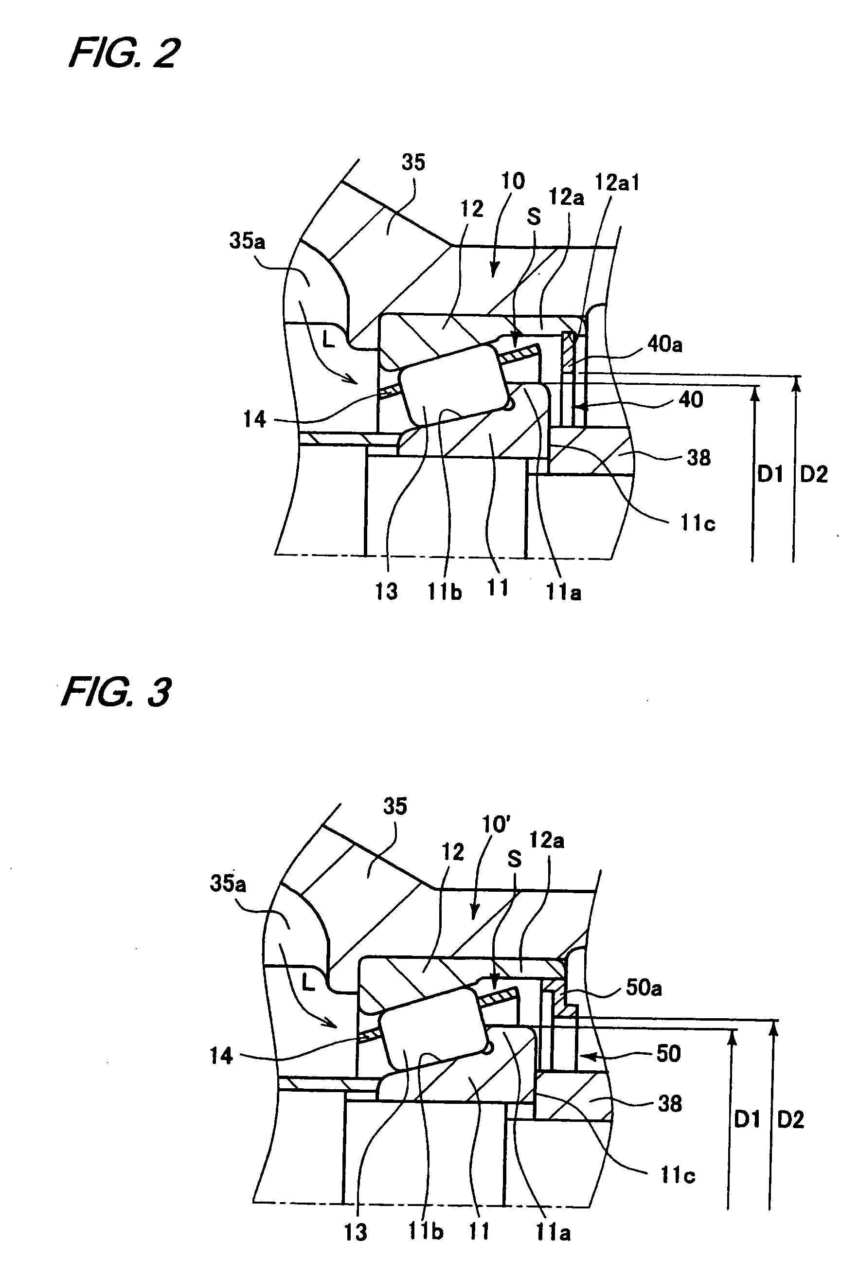
[0059] In the tapered roller bearing 10 of the above first embodiment, although the hole retaining ring 40 is used as the annular member, a deflector (annular member) 50 can be used instead of the hole retaining ring 40 as in a tapered roller bearing 10′ shown in FIG. 3. The other construction of the tapered roller bearing 10′ of this second embodiment shown in FIG. 3 is similar to that of the tapered roller bearing 10 of the first embodiment, and therefore identical members or corresponding members performing identical functions will be designated by identical reference numerals, respectively, and description thereof will be omitted.

[0060] The deflector 50 is usually called a Z-plate, and like the deflector 37, the deflector 50 is formed into an annular shape, and functions as a protective member for preventing the intrusion of foreign matters. In this second embodiment, the deflector 50 is fixed at its outer peripheral portion to an inner peripheral surface of an extension portio...

third embodiment

[0064]FIG. 6 is a side cross-sectional view of a further embodiment of a tapered roller bearing of the invention. This tapered roller bearing 210 comprises an inner ring (bearing ring) 211 for rotation with a rotation shaft 231, an outer ring (bearing ring) 212 fixed to a casing 235, a plurality of tapered rollers (rolling elements) 213 disposed between the inner and outer rings 211 and 212, and a cage 214 holding the tapered rollers 213 such that the tapered rollers 213 are arranged at predetermined intervals in a circumferential direction. A hole retaining ring (annular member) 240 is fixedly fitted in an engagement groove 212a1 formed in an inner peripheral surface of an extension portion 212a of the outer ring 212, and is disposed at a back face (211c) side of the inner ring 211 which is a lubricating oil discharge side. The hole retaining ring 240 has a ring-like plate portion 240a disposed parallel to the back face 211c of the inner ring 211. The hole retaining ring 240 is spa...


PUM


Abstract

An outer peripheral surface of an inner ring extends straight along outer peripheral surfaces of tapered rollers, and is open at a front side of a tapered roller bearing which is a lubricating oil supply side. A smaller-diameter end portion of a cage is cut in a radial direction to be open. A hole retaining ring is disposed at aback face side of the inner ring which is a lubricating oil discharge side, and is fixed at its outer peripheral portion to an inner peripheral portion of an extension portion of an outer ring. An inner diameter of the hole retaining ring is larger than an outer diameter of a larger rib portion of the inner ring.

Description

BACKGROUND OF THE INVENTION [0001] 1. Field of the Invention [0002] This invention relates to a tapered roller bearing and a differential gear apparatus employing tapered roller bearings. [0003] 2. Related Art [0004] Referring to a tapered roller bearing of the type described, for example, a pair of tapered roller bearings support a pinion shaft (having a pinion gear fixed to one end thereof) in a manner to allow the rotation of the pinion shaft about an axis thereof. The pair of tapered roller bearings are mounted within a differential case of a vehicle (such as an automobile) such the two bearings are spaced a predetermined distance from each other in the direction of the axis of the pinion shaft, and are arranged in back to back relation. Lubrication of each tapered roller bearing is effected by a so-called splash lubrication method in which lubricating oil within the differential case is splashed in accordance with the rotation of a ring gear driven by the pinion gear (see, for ...

Claims


Application Information

Patent Timeline
IPC IPC(8): F16H57/04F16C19/22F16C37/00F16C19/36F16C33/66F16H57/02F16H57/021
CPCF16C19/548F16C33/6655F16C33/6685F16H57/0471F16C19/364F16H2048/423F16H2057/02052F16C2361/61F16H57/0483F16C33/6651F16C33/583
Inventor ONO, KENICHI
Owner JTEKT CORP
Why Eureka
Try Eureka