Infusion pumps and methods and delivery devices and methods with same

a technology of pump and piston chamber, which is applied in the direction of engines without rotary main shafts, machines/engines, instruments, etc., can solve the problems that the manual insertion of the needle into the patient-user can be somewhat traumatizing to the patient-user, and achieve the effect of increasing the volume of reducing the fluid portion of the piston chamber

Inactive Publication Date: 2008-04-24
MEDTRONIC MIMIMED INC
View PDF99 Cites 172 Cited by
  • Summary
  • Abstract
  • Description
  • Claims
  • Application Information

AI Technical Summary

Benefits of technology

[0021]In the above pump embodiment, a push plate is supported for back-and-forth movement in a first direction and in a second direction opposite to the first direction. The push plate is arranged in a position for operative engagement with a drive shaft for movement of the push plate in the first direction as the drive shaft is moved in the first direction, and for allowing movement of the push plate in the second direction as the drive shaft is moved in the second direction. A piston head is supported for movement within the piston chamber between a retracted position and an active position to vary the volume of the fluid portion of the piston chamber. The piston head is operatively coupled in a fixed relation to the push plate, for movement from the retracted position to the active position with movement of the push plate in the first direction.
[0026]Supporting the pump device further includes arranging a piston head within the piston chamber for movement between a retracted position and an active position to vary the volume of the fluid portion of the piston chamber, and coupling the piston head in a fixed relation to the push plate, for movement from the retracted position to the active position with movement of the push plate in the first direction. In such a method, when the piston chamber contains infusion fluid, the volume of the fluid portion of the piston chamber is reduced as the piston head is moved from the retracted position to the active position to provide a pressure within the piston chamber to force the infusion fluid from the fluid portion of the piston chamber and through the outlet port. In addition, the volume of the fluid portion of the piston chamber is increased as the piston head is moved from the retracted position to the active position to provide a pressure within the piston chamber to draw infusion fluid into the fluid portion of the piston chamber, through the inlet port, when the inlet port is connected in fluid flow communication with a reservoir.
[0042]Also, such further methods include providing an inlet port extending to the piston channel and configured for connection to a source of fluidic medium and providing an outlet port in fluid flow communication with the piston channel. In addition, such methods include providing a piston having a surface for receiving a drive force from the drive shaft when the disposable housing portion and the durable housing portion are engaged for operation, and supporting the piston in the piston channel for movement along the longitudinal axis of the piston channel between fill and dispense positions upon receiving a force from a drive shaft. In the fill position, the piston is moved to a position to allow fluid flow communication through the inlet port and into the piston channel and piston chamber. In the dispense position, the piston is moved to a position to obstruct fluid flow communication through the inlet port and to reduce the volume of the piston chamber to force fluid in the piston chamber out of the outlet port.
[0045]A piston is located in the piston channel and has a surface for receiving a drive force from the drive shaft when the durable housing portion and disposable hosing portion are engaged. The piston is moveable with movement of the drive shaft along the longitudinal axis of the piston channel between fill and dispense positions. In the fill position, the piston is moved to a position to allow fluid flow communication through the inlet port and into the piston channel and piston chamber. In the dispense position, the piston is moved to a position to obstruct fluid flow communication through the inlet port and to reduce the volume of the piston chamber to force fluid in the piston chamber out of the outlet port.

Problems solved by technology

In contexts in which the hollow tubing is connected to the patient-user through a hollow needle that pierces the patient-user's skin, a manual insertion of the needle into the patient-user can be somewhat traumatic to the patient-user.

Method used


Image

  • Infusion pumps and methods and delivery devices and methods with same
  • Infusion pumps and methods and delivery devices and methods with same
  • Infusion pumps and methods and delivery devices and methods with same

Examples


Embodiment Construction

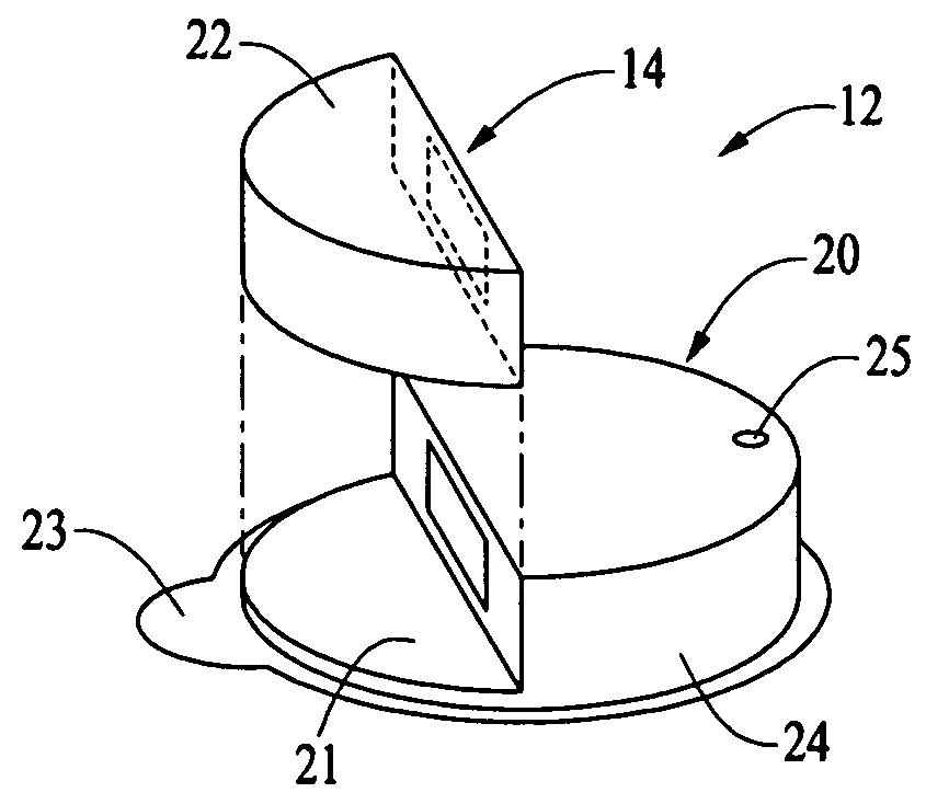
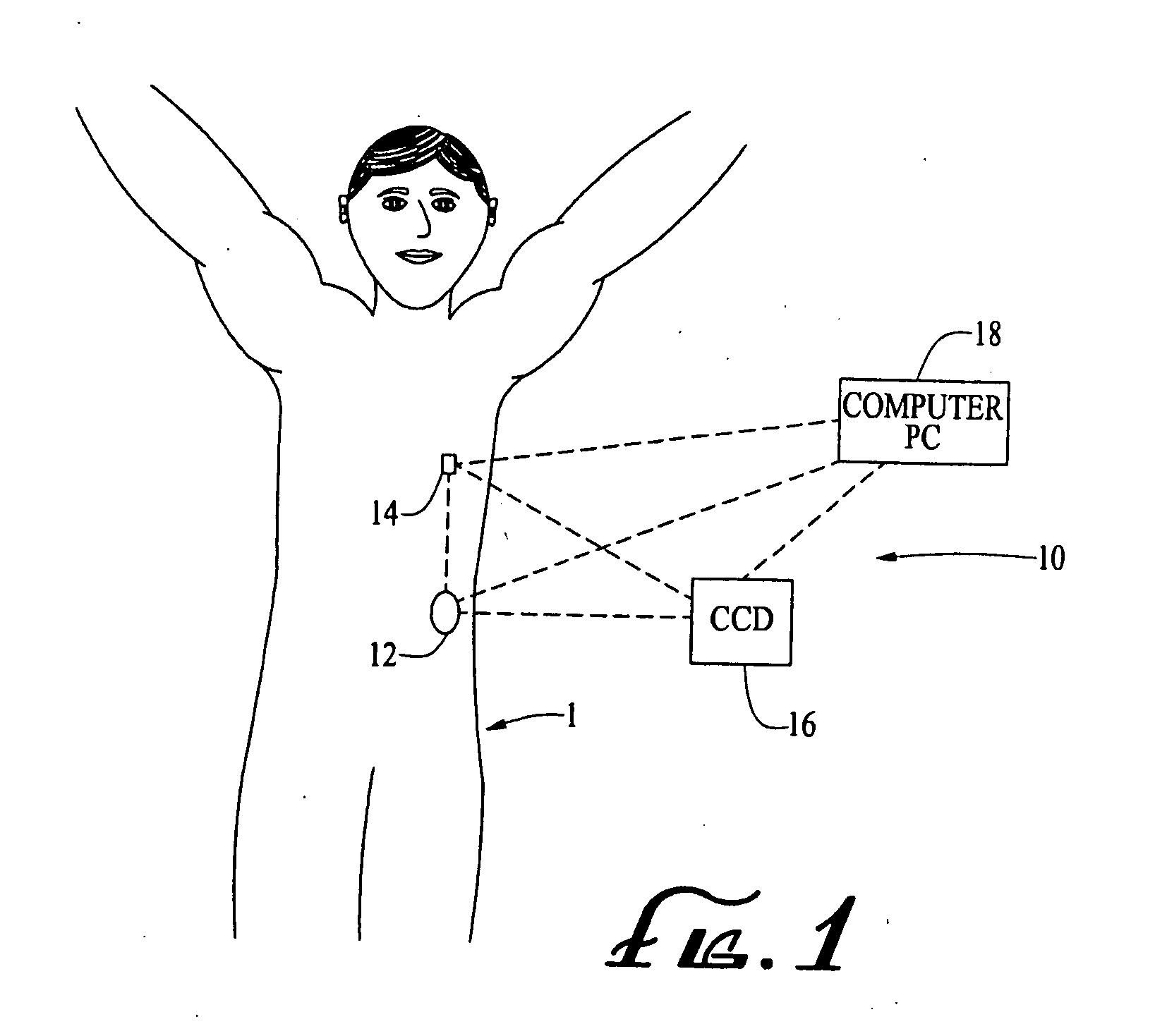
[0079]The present invention relates, generally, to delivery devices, systems and methods for delivering an infusion medium, such as a drug, to a recipient, such as a medical patient. In particular embodiments, a delivery device includes first and second housing portions (referred to herein as a durable housing portion and a disposable housing portion, respectively) that are configured to engage and attach to each other for operation. The disposable housing portion may contain or otherwise support an infusion medium reservoir and other components that come into contact with the infusion medium and / or the patient-user during operation. The disposable housing portion may also contain or otherwise support a pump device in accordance with one of the embodiments described herein. The pump device is connected or connectable in fluid flow communication with the reservoir, to draw fluid from the reservoir and / or convey the fluid to an injection site.

[0080]The disposable housing portion may b...


PUM

PropertyMeasurementUnit
interior volumeaaaaaaaaaa
volumeaaaaaaaaaa
pressureaaaaaaaaaa

Abstract

A delivery device includes a durable housing portion and a separable disposable portion that selectively engage and disengage from each other. The disposable housing portion secures to the patient-user and may be disposed of after it has been in use for a prescribed period. Components that normally come into contact with a patient-user or with an infusion medium, including a pump device, are supported by the disposable housing portion for disposal after the prescribed use, while the durable housing portion supports other components such as electronics for controlling delivery of the infusion medium from the reservoir and a drive device and drive linkage.

Description

CROSS-REFERENCE TO RELATED PATENT APPLICATIONS[0001]The present invention relates to U.S. Application 60 / 839,741, filed Aug. 23, 2006, titled “Infusion Pumps And Methods And Delivery Devices And Methods With Same,” which is incorporated herein by reference in its entirety and from which a priority filing date is claimed. The present invention also relates to U.S. Patent Application No. 60 / 678,290, filed May 6, 2005 and U.S. patent application Ser. No. 11 / 211,095, filed Aug. 23, 2005, titled “Infusion Device And Method With Disposable Portion,” each of which is incorporated herein by reference in its entirety and from which the priority filing date is claimed. The present invention also relates to co-pending U.S. patent application No. 60 / 839,821, filed Aug. 23, 2006, titled “Infusion Medium Delivery Device And Method For Driving Plunger In Reservoir” (attorney docket no. 047711.0381); co-pending U.S. patent application No. 60 / 839,822, filed Aug. 23, 2006, titled “Infusion Medium Del...

Claims


Application Information

Patent Timeline
Patent Type & Authority Applications(United States)
IPC IPC(8): A61M31/00F01B11/08B21D53/00
CPCA61M5/1413A61M5/14216A61M5/14248A61M5/14566A61M5/385A61M2005/14268Y10T29/49826A61M2205/8206A61M2209/045G01F11/021G01F11/023G01F11/029G01F11/06A61M2205/0266
Inventor HANSON, IAN B.BENTE, PAUL F.MOUNCE, R. PAULCHONG, COLIN A.
Owner MEDTRONIC MIMIMED INC
Why Eureka
Try Eureka