Temperature controlled multi-gas distribution assembly

a technology of temperature control and assembly, applied in the direction of coating, chemical vapor deposition coating, metallic material coating process, etc., can solve the problems of deterioration of the device or other parts of the processing chamber, affecting the effect of temperature control, and increasing the presence of unwanted particles

Inactive Publication Date: 2008-05-01
APPLIED MATERIALS INC
View PDF31 Cites 447 Cited by
  • Summary
  • Abstract
  • Description
  • Claims
  • Application Information

AI Technical Summary

Benefits of technology

[0017]So that the manner in which the above recited features of the present invention can be understood in detail, a more particular description of the invention, briefly summarized above, may be had by reference to embodiments, some of which are illustrated in the appended drawings. It is to be noted, however, that the appended drawings illustrate only typical embodiments of this invention and are therefore not to be considered limiting of its scope, for the invention may admit to other equally effective embodiments. Nonetheless, the teachings of the present invention can be readily understood by considering the following detailed description in conjunction with the accompanying drawings, in which:

Problems solved by technology

Additionally, reaction by products may accumulate in the chamber gas delivery components or on the inside surface of the distribution plate, thus generating, and / or increasing the presence of, unwanted particles.
While some gas distribution devices have been developed to minimize gas mixing prior to entry into the processing region, the devices may tend to prematurely deteriorate during processing.
For example, conventional distribution devices may be made of materials that expand and contract during processing, leading to deterioration of the device or other parts of the processing chamber.
The conventional devices may also require sealing with large elastomeric seals, such as large diameter o-rings that may deteriorate over time, which may lead to leaks within the device.
Further, conventional devices that deliver two or more gases to the processing region may not mix uniformly in the processing region, thus leading to non-uniform deposition on the substrate.

Method used


Image

  • Temperature controlled multi-gas distribution assembly
  • Temperature controlled multi-gas distribution assembly
  • Temperature controlled multi-gas distribution assembly

Examples


Embodiment Construction

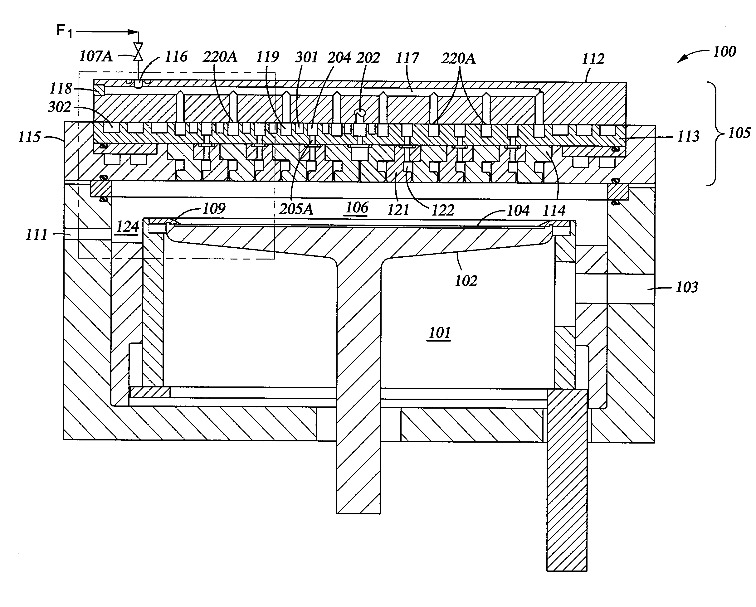
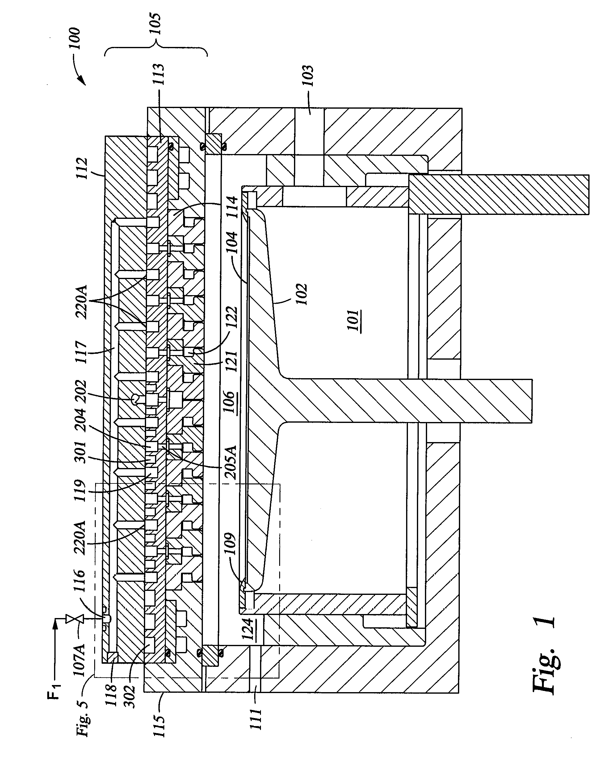
[0027]FIG. 1 is a cross-sectional view of one embodiment of a processing chamber 100. The processing chamber 100 includes a substrate support 102 disposed within an interior volume 101. A substrate 104, such as a semiconductor wafer, may enter and exit the interior volume 101 by an opening 103 disposed in a wall of the processing chamber 100. Chamber 100 also includes a lid assembly 105 coupled to an upper surface thereof, which forms a boundary for at least a portion of the interior volume 101. In this embodiment, lid assembly 105 comprises a lid plate 112, an upper manifold 113 in fluid communication with lid plate 112, a lower manifold 114 in fluid communication with upper manifold 113, and a lid ring 115.

[0028]In one embodiment, a lower surface of the lid assembly 105 and the upper surface of the substrate 104 define a processing region 106. Lower manifold 114 of lid assembly 105 is in fluid communication with processing region 106. In a specific embodiment, the processing chamb...


PUM

PropertyMeasurementUnit
widthaaaaaaaaaa
widthaaaaaaaaaa
thermal energyaaaaaaaaaa

Abstract

An apparatus and method for a gas distribution plate is provided. The gas distribution plate has a first manifold which includes a plurality of concentric channels for providing at least two distinct gases to a processing zone above a substrate. A portion of the plurality of channels perform a thermal control function and are separated from the remaining channels, which provide separated gas flow channels within the gas distribution plate. The gas flow channels are in fluid communication with a second manifold which includes a plurality of concentric rings. Apertures formed in the rings are in fluid communication with the gas flow channels and the processing zone. The gases are provided to the processing zone above the substrate, and do not mix within the gas distribution plate.

Description

BACKGROUND OF THE INVENTION[0001]1. Field of the Invention[0002]The invention relates to an apparatus for processing substrates, such as semiconductor wafers, and more particularly, to an apparatus for distribution of process fluids over a substrate.[0003]2. Description of the Related Art[0004]Semiconductor processing systems generally include a process chamber having a pedestal for supporting a substrate, such as a semiconductor wafer, within the chamber proximate a processing region. The chamber forms a vacuum enclosure defining, in part, the processing region. A gas distribution assembly or showerhead provides one or more process gases to the processing region. The gases are then heated and / or energized to form a plasma which performs certain processes upon the substrate. These processes may include deposition processes, such as chemical vapor deposition (CVD), to deposit a film upon the substrate or an etch reaction to remove material from the substrate, among other processes.[0...

Claims


Application Information

Patent Timeline
Patent Type & Authority Applications(United States)
IPC IPC(8): C23F1/00C23C16/00
CPCC23C16/45565C23C16/45574C23C16/45572H01L21/3065H01L21/205H01L21/02H01L21/31
Inventor MYO, NYI OOPOPPE, STEVENMATTINGER, GEORGE
Owner APPLIED MATERIALS INC
Why Eureka
Try Eureka