

Coulomb damped disc brake rotor and method of manufacturing
a technology of coulomb and disc brake, which is applied in the direction of braking discs, friction linings, mechanical instruments, etc., can solve the problems of requiring a significant amount of testing and analytical resources, and the brake squeal may be undesirable, so as to prevent bonding and reduce the external exposure of the coulomb damper inser
- Summary
- Abstract
- Description
- Claims
- Application Information
AI Technical Summary
Benefits of technology
Problems solved by technology
Method used
Image

Examples
Embodiment Construction
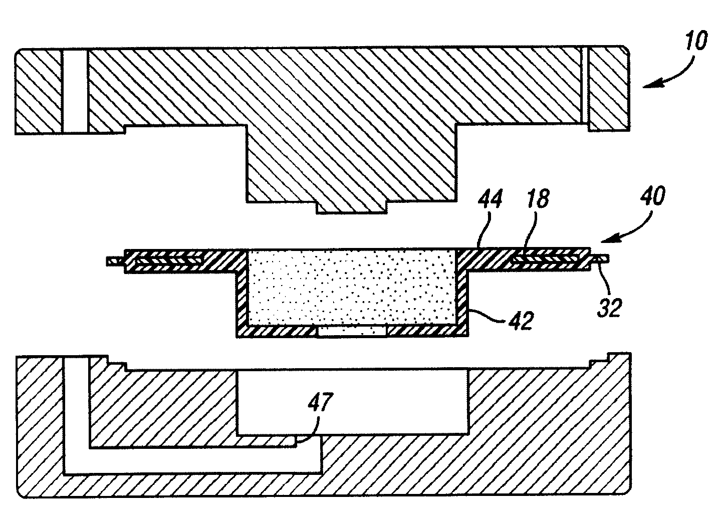
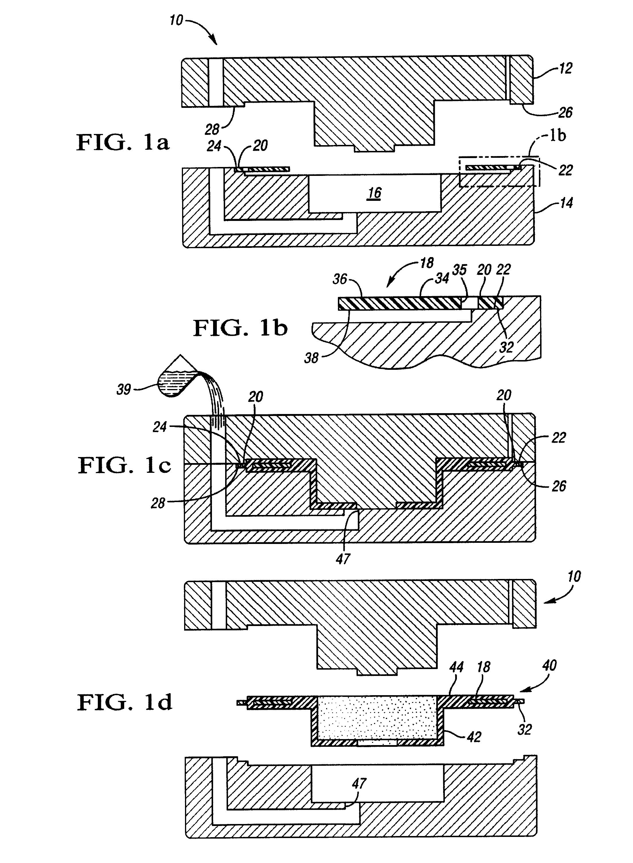
[0016]Referring to FIGS. 1a and 1b, a mold 10 in accordance with the invention having upper and lower mold halves 12, 14 that form a cavity 16 therebetween for casting a friction damped disc brake rotor in accordance with the invention. FIG. 1b shows a portion of a coulomb damper insert 18, highlighted in FIG. 1a, which is pre-positioned within the mold 10 and having tabs 20 which rest on cutout portions 22, 24 of the lower mold half 14. As shown in FIG. 1c, when the upper and lower mold halves 12, 14 are closed together, the tabs 20 are supported between the cutout portions 22, 24 of the lower mold half 14 and the lands 26, 28, respectively of the upper mold half 12.
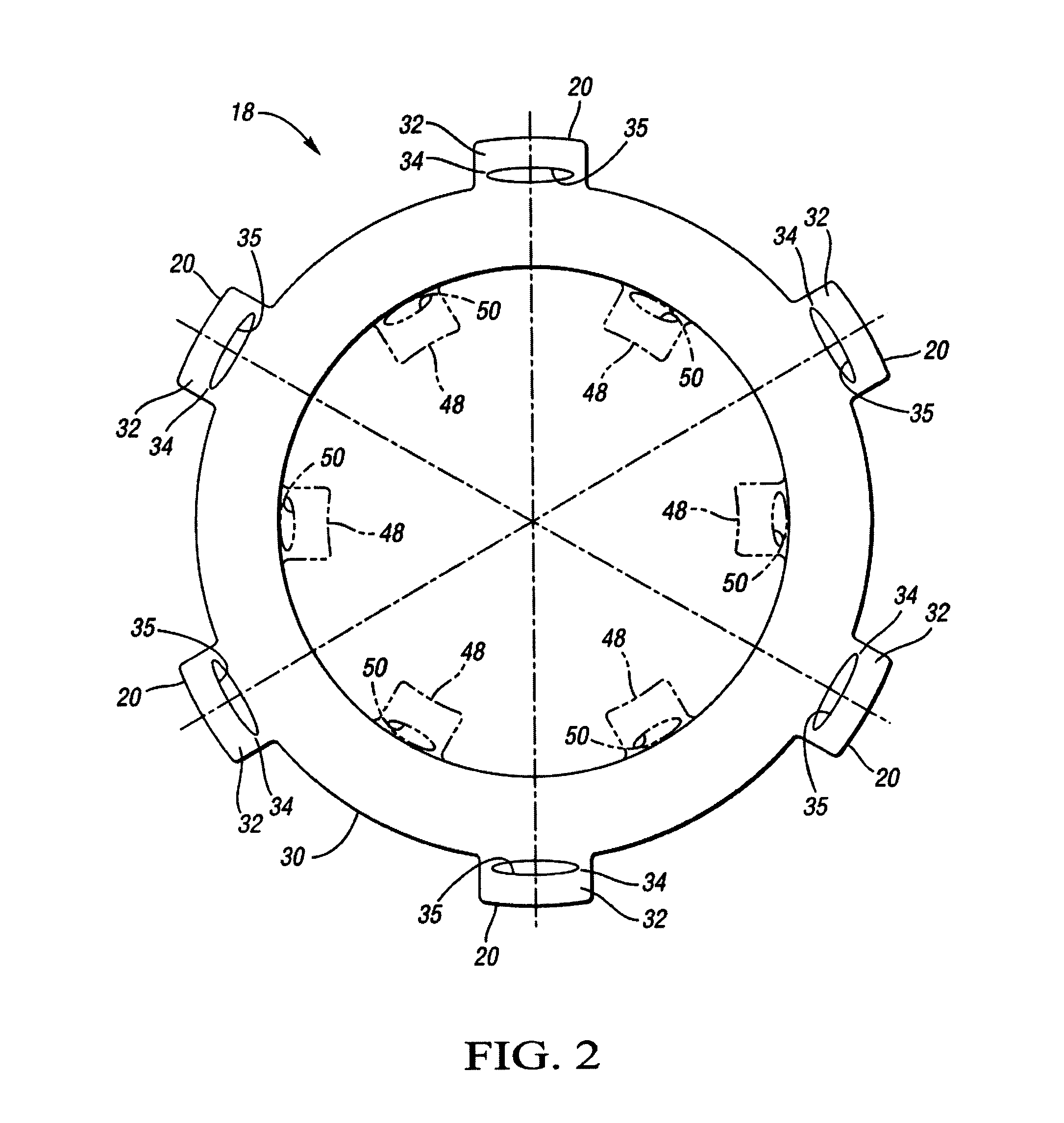
[0017]Referring to FIG. 2, the coulomb damper insert 18 is shown in plan view. As shown, the coulomb damper insert 18 has a generally annular body 30 with tabs 20 extending therefrom. Each tab includes a distal portion 32 and a proximal portion 34. During casting, the distal portion 32 is secured between the cutout port...
PUM
| Property | Measurement | Unit |
|---|---|---|
| Thickness | aaaaa | aaaaa |
| Thickness | aaaaa | aaaaa |
| Thickness | aaaaa | aaaaa |
Abstract
Description
Claims
Application Information