Electrostatic Voltmeter

a technology of electrostatic voltage and voltmeter, which is applied in the direction of electrostatic field measurement, instruments, measurement devices, etc., can solve the problems of inability to successfully perform contacting or non-contacting electrostatic voltage measurement, input capacitance of the sensor, and substantial distortion

Inactive Publication Date: 2008-05-01
TREK BICYCLE CORPORATION
View PDF8 Cites 17 Cited by
  • Summary
  • Abstract
  • Description
  • Claims
  • Application Information

AI Technical Summary

Benefits of technology

[0009]The invention may include an electrostatic voltmeter having an input sensing terminal, a first operational amplifier (“amplifier A1”), a second operational amplifier (“amplifier A2”), a first reference voltage terminal, a low reference voltage terminal and a voltage indicator. The amplifier A1, may have a non-inverting input, an inverting input and an output, the non-inverting input being electrically connected to the input sensing terminal, and the inverting input being electrically connected to the output to create a voltage follower. Amplifier A2 may have a no...

Problems solved by technology

A challenge associated with electrostatic voltage metrology is to perform the measurement without disturbing the electrical state of the measured surface/object.
The detrimental effect that the input capacitance of the sensor has on electrostatic voltage measurements is with the electrical charge required to be supplied by the measured electrostatic object to drive the input capacitance of the sensor to the measured object's voltage level.
Prior art contacting electrostatic voltmeters and devices, i.e., electrometers, typically feature an input capacitance of 1×10⁻¹⁵ farad with input bias currents of 1×10⁻¹⁵ amps with input resistances of 1015 ohms (see U.S. Pat. No. 3,870,968), and so they cannot be used successfully to perform contacting or noncontacting electrostatic voltage measurements without causing substantial distortion to the initial electrical state of the contacted measured object or producing measurement error when making noncontacting measurements.
If the input capacitance of these devices is lowered to a value in the order of 10−16 farads, the 10−14 input current would produce an uncontrollable input drift rate due to the input current providing a large source into...

Method used


Image

  • Electrostatic Voltmeter
  • Electrostatic Voltmeter
  • Electrostatic Voltmeter

Examples


Embodiment Construction

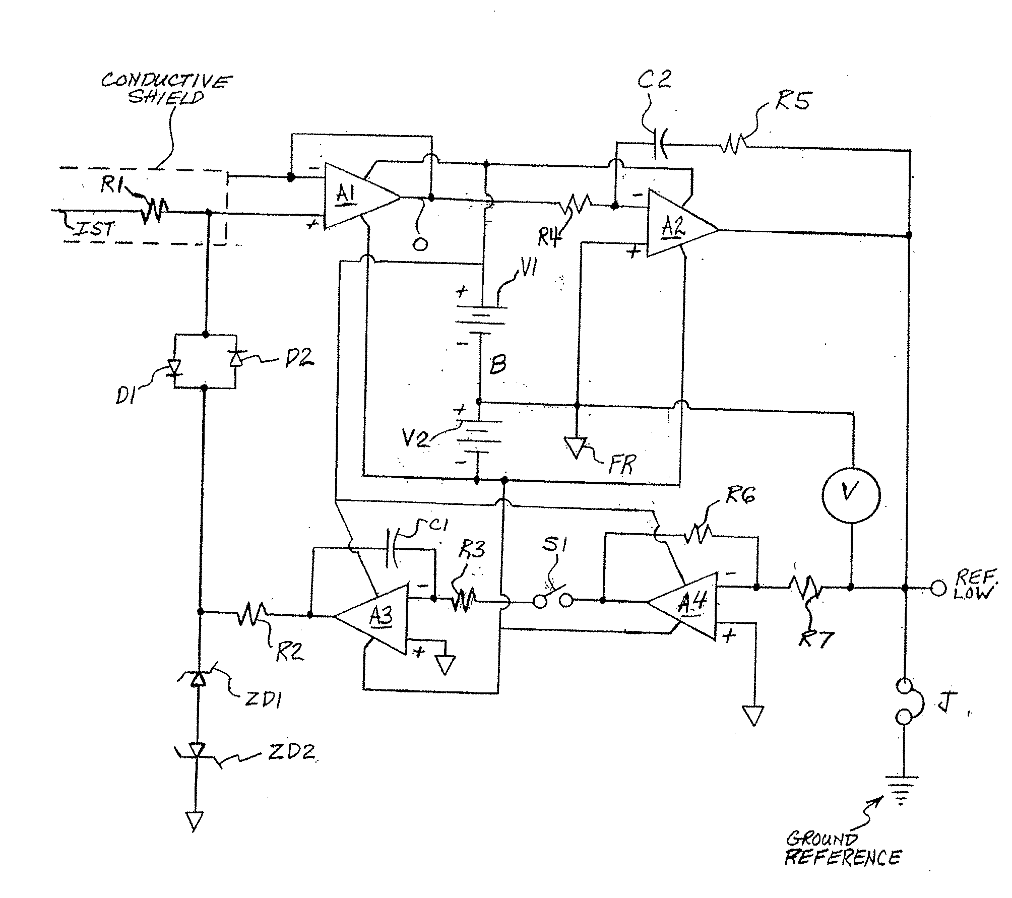
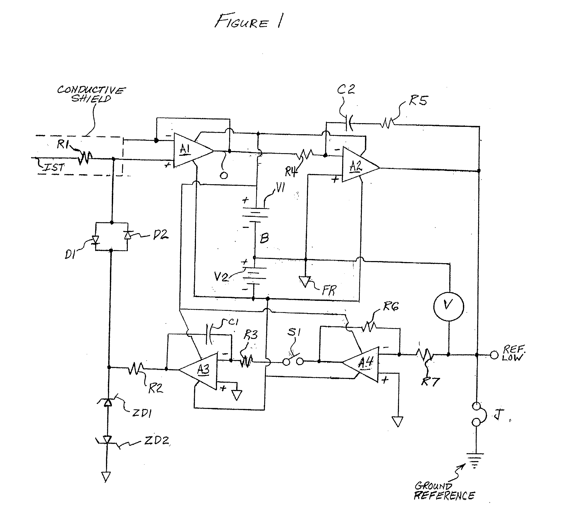
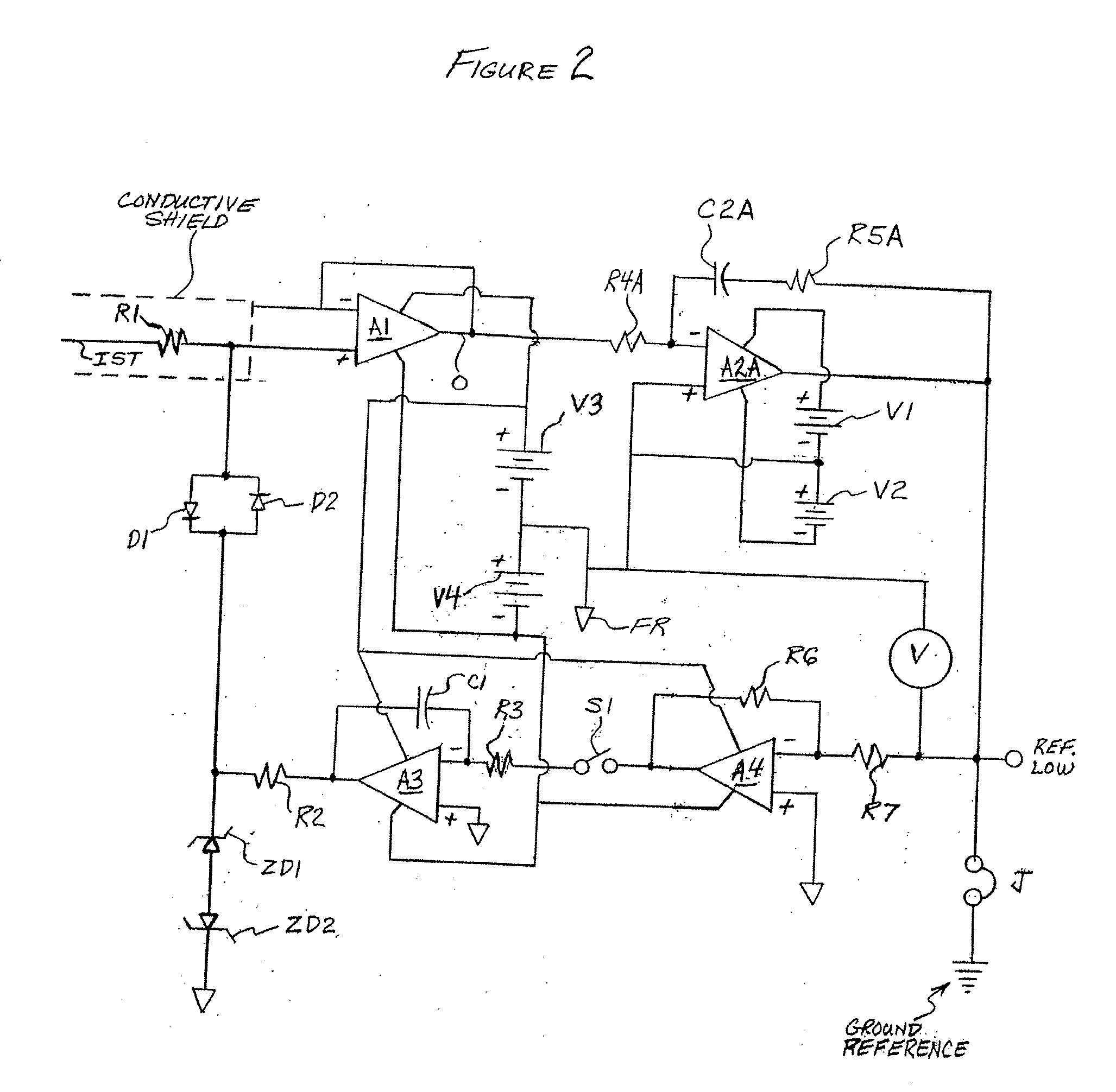
[0015]An embodiment of the invention is described herein which may provide one or more of the following advantages:[0016]1. input capacitance of less than 1×10⁻¹⁷ farads[0017]2. input bias current of less than 1×10⁻¹⁹ amps[0018]3. measurement bandwidth of greater than 50 kHz[0019]4. a method of initializing the voltage level of the follower's input circuitry at zero volts to prevent charge transfer to / from the measured object upon initial contact, the zeroing method avoiding an offset voltage jump shift at the input upon release of the zeroing circuitry devices.[0020]5. a method to produce nullification of the follower's input bias current and / or other leakage currents without the requirement to intentionally generate a voltage offset between the follower's input and output thus preventing current flow to the input capacitance when making noncontacting measurements, or current flow to the measured object when making contacting measurements.[0021]6. an easy-to-use, portable measureme...


PUM


Abstract

An electrostatic voltmeter has an input sensing terminal, a first operational amplifier, a second operational amplifier, a first reference voltage terminal electrically connected to the non-inverting input of the second operational amplifier, a low reference voltage terminal electrically connected to the output of the second operational amplifier, and a voltage indicator, electrically connected between the low reference voltage terminal and the first reference voltage terminal.

Description

FIELD OF THE INVENTION[0001]The present invention relates to electrostatic voltmeters for contacting or non-contacting measurements.BACKGROUND OF THE INVENTION[0002]A challenge associated with electrostatic voltage metrology is to perform the measurement without disturbing the electrical state of the measured surface / object. This condition can only be accomplished by a device / instrument that has an input resistance of extremely high value, much higher than that of the measured electrostatic system / surface / object being measured. This high input resistance limits the amount of electric charge migrating between the measuring device and the object under test when performing contacting measurements.[0003]Another factor influencing the measuring device's capability for electrostatic voltage measurement is the amount of input capacitance associated with the measurement device's input sensor circuitry, together with the parallel capacitance associated with any connection circuits to the sen...

Claims


Application Information

Patent Timeline
IPC IPC(8): G01R29/12
CPCG01R19/0023
Inventor WILLIAMS, BRUCE T.
Owner TREK BICYCLE CORPORATION
Why Eureka
Try Eureka