
Heat-dissipating assembly structure

Inactive Publication Date: 2008-05-01
CHEN CHIUNG YI
View PDF12 Cites 24 Cited by
  • Summary
  • Abstract
  • Description
  • Claims
  • Application Information

AI Technical Summary

Benefits of technology

[0007]The present invention has been accomplished under the circumstances in view. It is the main object of the present invention to provide a heat-dissipating assembly structure, which can easily and closely be secured to the memory chips of a memory module to dissipate heat from the memory chips efficiently. It is another object of the present invention to provide a heat-dissipating assembly structure, which can easily and rapidly be assembled and installed.

Problems solved by technology

However, a high-speed IC chip products much heat energy during operation.
If heat energy is not rapidly removed from the surface of the IC chip during its operation, the IC chip may be unable to function normally or may burn out when the working temperature surpasses a predetermined level.
However, a fan-heat-dissipating assembly is not practical for use in a narrow space area, or where the contact area between the heat source and the air is limited.
When fan-heat-dissipating assembly is used in a narrow space area or where the contact area between the heat source and the air is limited, the amount of currents of air blowing toward the heat source at a unit of time is limited, resulting in low heat dissipation efficiency.
Further, the installation of this design of heat-dissipating assembly structure needs much labor.

Method used


Image

  • Heat-dissipating assembly structure
  • Heat-dissipating assembly structure
  • Heat-dissipating assembly structure

Examples


Embodiment Construction

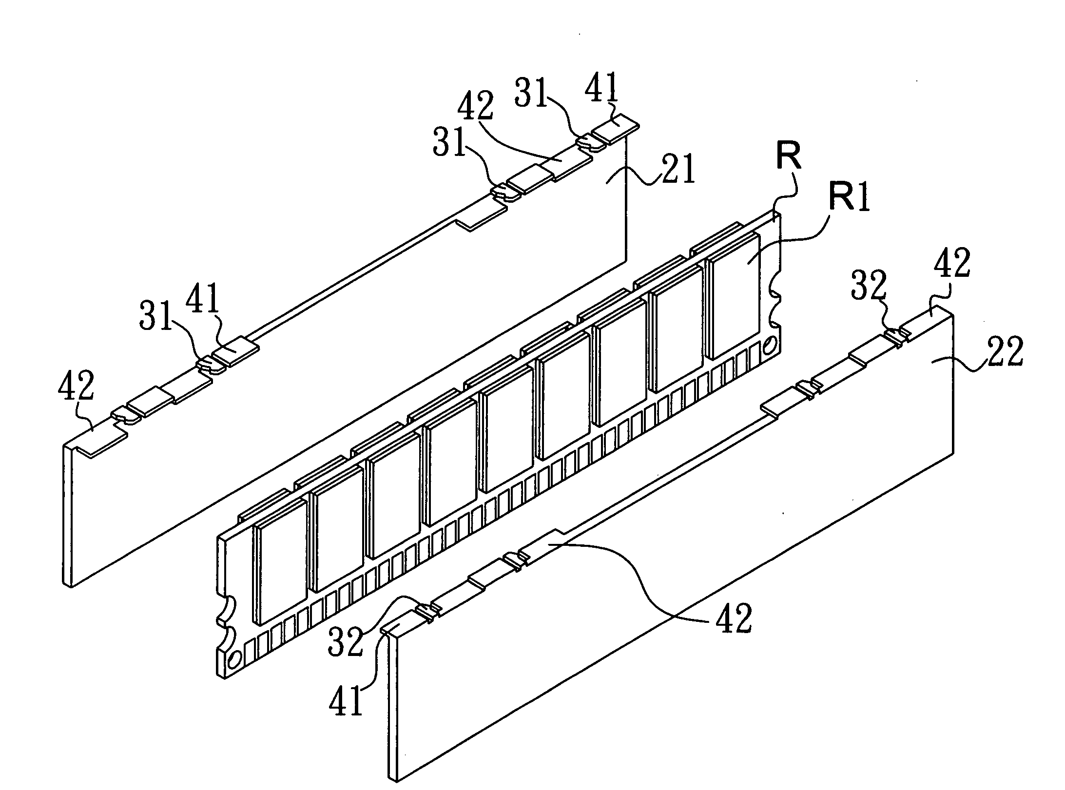
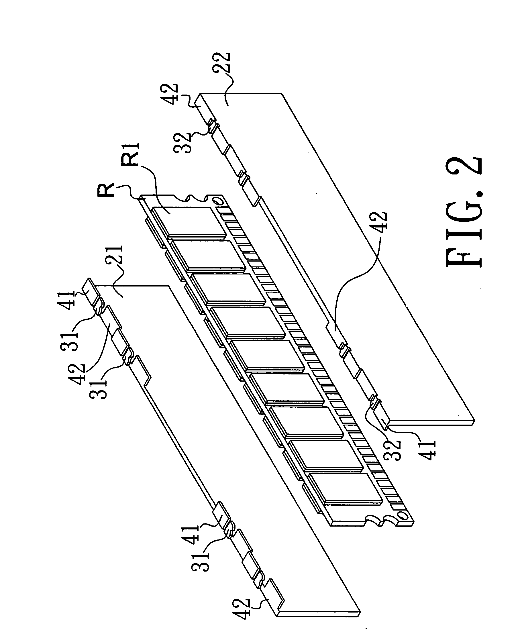
[0016]Referring to FIGS. 2˜4, a heat-dissipating assembly structure in accordance with the present invention is shown fastened to a memory module R and adapted to dissipate heat from the memory module R. The heat-dissipating assembly structure is comprised of a left heat dissipating sheet 21, a right heat dissipating sheet 22, first hooks 31, second hooks 32, and at least one guide plate pair each having a first guide plate 41 and a second guide plate 42 disposed at different elevations.

[0017]The left heat dissipating sheet 21 and the right heat dissipating sheet 22 are respectively attached to the left and right sides of the memory module R (see FIG. 3). The left heat dissipating sheet 21 and the right heat dissipating sheet 22 are made of copper or aluminum alloy for the advantage of high heat conductivity for quick dissipation of heat energy. Further, the left heat dissipating sheet 21 and the right heat dissipating sheet 22 have a rectangular shape and are symmetrically attached...


PUM


Abstract

A heat-dissipating assembly structure includes a first heat dissipating sheet attached to one side of a memory module and having first hooks at one long side, a second heat dissipating sheet attached to the opposite side of the memory module and having second hooks at one long side respectively hooked up with the first hooks, and pairs of guide plates respectively provided at the same long side of the left heat dissipating sheet and the same long side of the right heat dissipating sheet at different elevations for guiding the first hooks into engagement with the second hooks during installation of the heat-dissipating assembly structure.

Description

BACKGROUND OF THE INVENTION[0001]1. Field of the Invention[0002]The present invention relates to a heat-dissipating assembly structure for memory module and more particularly, to such a heat-dissipating assembly structure that can easily and closely secured to the memory chips of a memory module to dissipate heat from the memory chips efficiently.[0003]2. Description of the Related Art[0004]Following fast development of high technology, advanced and high power IC chips are continuously created. However, a high-speed IC chip products much heat energy during operation. If heat energy is not rapidly removed from the surface of the IC chip during its operation, the IC chip may be unable to function normally or may burn out when the working temperature surpasses a predetermined level. Many heat dissipation devices have been produced for dissipating heat from semiconductor products. Subject to heat dissipation principle and the type of heat dissipation medium, regular heat dissipation dev...

Claims


Application Information

Patent Timeline
IPC IPC(8): H05K7/20
CPCH01L23/4093H01L2924/0002H01L2924/00
Inventor CHEN, CHIUNG YI
Owner CHEN CHIUNG YI
Features
  • Generate Ideas
  • Intellectual Property
  • Life Sciences
  • Materials
  • Tech Scout
  • Unparalleled Data Quality
  • Higher Quality Content
  • 60% Fewer Hallucinations
Learn More