High efficient compact radial blower

a radial blower, compact technology, applied in the direction of positive displacement liquid engines, piston pumps, liquid fuel engines, etc., can solve the problems of requiring improved systems for heat removal, large power supplies and auxiliary components that generate increased amounts of heat, and premature device failure, so as to improve blower performance and reduce sound. the effect of the level of efficiency

Inactive Publication Date: 2008-05-01
INDAL DESIGN LAB
View PDF0 Cites 31 Cited by
  • Summary
  • Abstract
  • Description
  • Claims
  • Application Information

AI Technical Summary

Benefits of technology

[0013]Accordingly, it is an object of the present invention to provide a high efficient compact radial blower for electronic device, which is capable of significantly improving of blower performances such as smaller dimensions, especially thickness, decreased sound level and increased blower efficiency.

Problems solved by technology

Cooling is important because if left unchecked, heat can cause electronic devices to malfunction during use or lead to premature device failure.
Additionally, improved processors require larger power supplies and auxiliary components that generate increased amounts of heat and require improved systems for heat removal.
The trend toward smaller and thinner electronic devices having larger, faster processors renders the traditional heat removal cooling systems inadequate for several reasons.
By this reason, the thermal efficiency of this heat dissipation device is insufficient.
However, such arrangement cause a vibration of the flat stator and magnetized rotor due to a rise of oscillation forces in a direction perpendicular to the planes of the flat stator and the magnetized rotor.
In one's turn the vibration generates an increasing sound level thus contradicts with modern requirements for cooling devices.
On the other hand mentioned vibration causes energy losses thus decrease the motor efficiency of the electric drive and, correspondingly, blower efficiency.
However such design requires additional space for placement of mentioned magnets portions.

Method used


Image

  • High efficient compact radial blower
  • High efficient compact radial blower
  • High efficient compact radial blower

Examples


Embodiment Construction

[0049]Preferred embodiments of the present invention will be described in detail below with reference to the accompanying drawings.

[0050]FIGS. 1-18 show embodiments of the present invention.

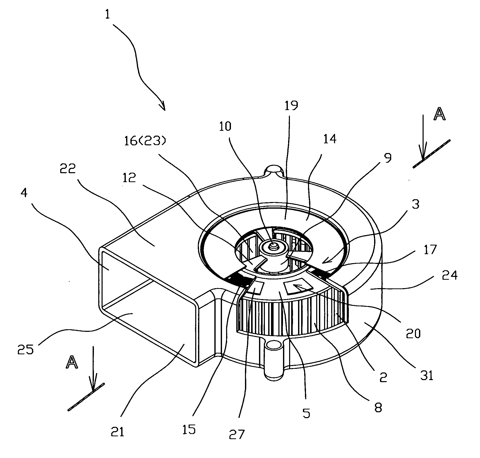
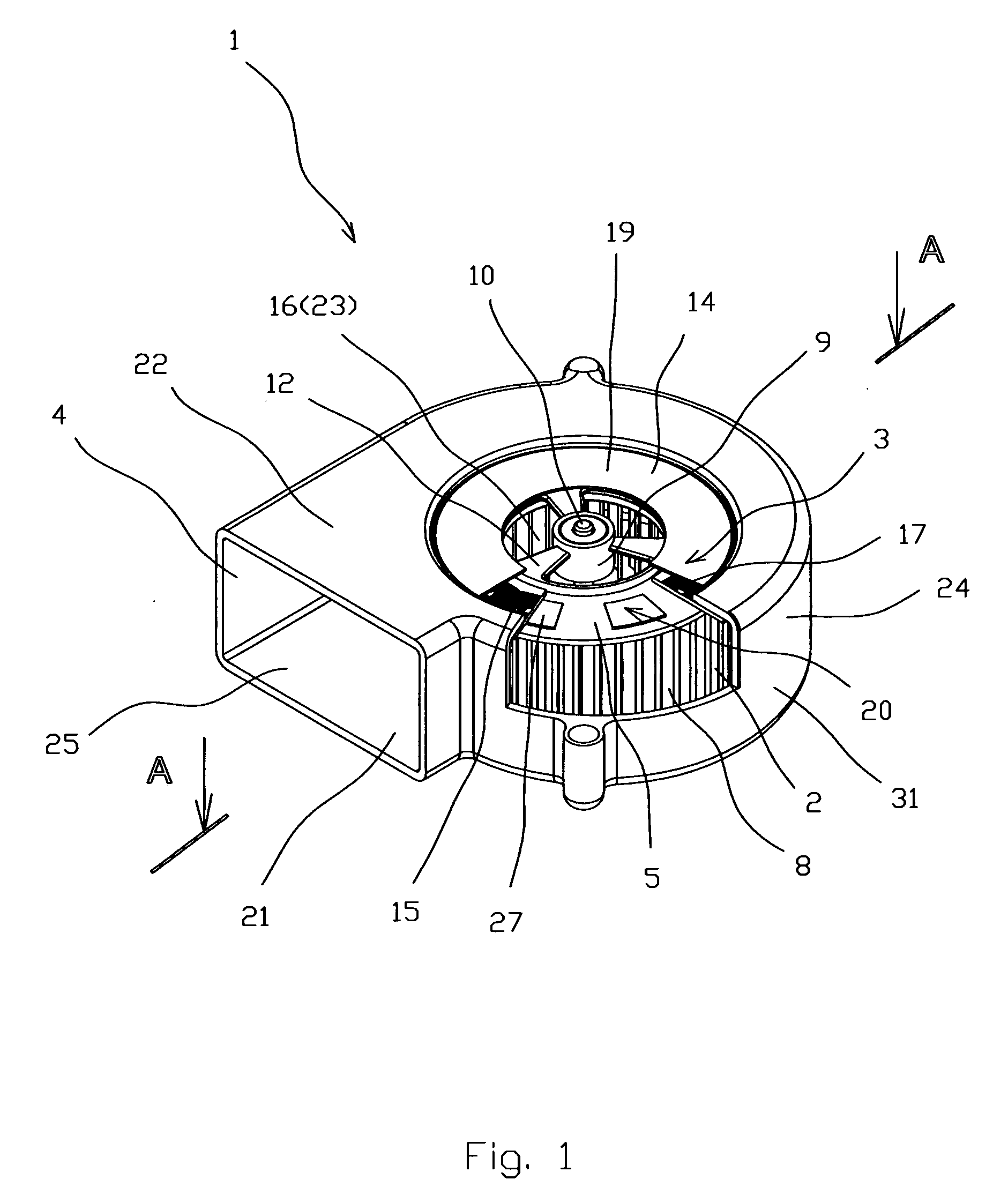
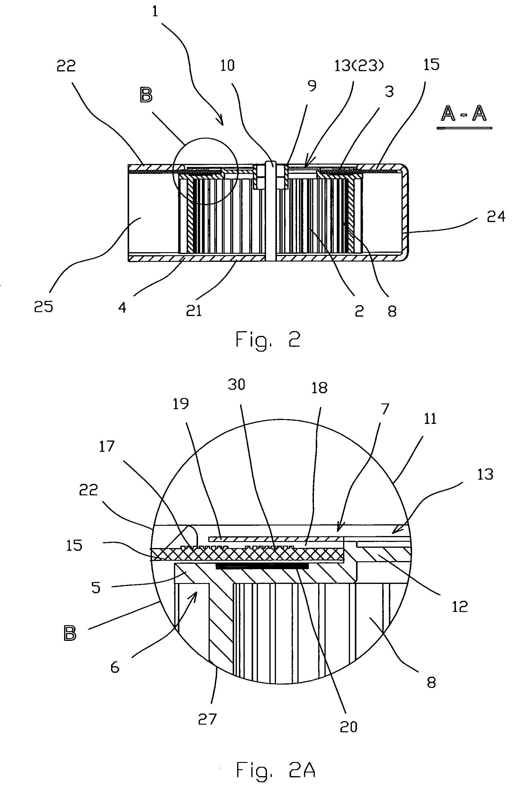
[0051]The high efficient compact radial blower 1 according to the first embodiment (FIGS. 1-10 comprises an impeller 2, an electric drive 3 and a housing 4. The impeller 2 comprises an impeller disk 5 with the first 6 and second 7 sides, radial blades 8 protruded from the first side 6, a central hub 9 mounting on an axle 10, and an inflow hub 11 integrated with the impeller disk 5. The inflow hub 11 rigidly fixed with the central hub 9 by at least 2 brackets 12, thus forms an impeller inlet 13. The electric drive 3 comprises a magnetized rotor 14 located from the second side 7 of the impeller disk 5 and a stator 15 with a central opening 16 surrounded by circumferentially arrayed flat coil windings 17 having magnetic axes parallel to the axle 10. The magnetized rotor 14 comprises spaced apart by ...


PUM


Abstract

A radial blower comprising an impeller, an electric drive and a housing. The impeller comprises an impeller disk with the first and second sides, radial blades protruded from the first side, a central hub mounting on an axle, and an inflow hub integrated with the impeller disk. The electric drive comprises a magnetized rotor located from the second side of the impeller disk and a stator with a central opening surrounded by circumferentially arrayed flat coil windings. The magnetized rotor comprises spaced apart by an axial gap a flat ferromagnetic ring and a layer of magnetic means. The housing comprises a base, a shaped upper side, and a side part. The shaped upper side at least partially surrounds the magnetized rotor. The stator at the outer is rigidly bounded with the shaped upper side while the inner part of the stator is placed at the axial gap.

Description

CROSS REFERENCE TO RELATED APPLICATIONS[0001]The present application claims the benefit of priority of U.S. Provisional Patent Application No. 60 / 855,068 filed Oct. 27, 2006 for Edward Lopatinsky et al. the entire content of which is incorporated herein by reference.FIELD OF THE INVENTION[0002]The present invention relates generally to radial type impeller blowers for cooling of electronic devices. More particularly, the present invention relates to relative thin blowers. The present invention is particularly, but not exclusively, useful for cooling systems for regulating the temperature of electronic components of blade servers.BACKGROUND OF THE INVENTION[0003]The regulation of the temperature due to heat generated inside the housing of an electronic device is an important consideration during the design of an electronic device. Cooling is important because if left unchecked, heat can cause electronic devices to malfunction during use or lead to premature device failure. As improve...

Claims


Application Information

Patent Timeline
Patent Type & Authority Applications(United States)
IPC IPC(8): H02K9/06
CPCF04D25/0653F04D29/282F04D29/4213F04D29/441H02K21/24H02K1/2793H02K3/26H02K7/14H02K9/06F04D29/582F05D2250/51H02K1/2795
Inventor LOPATINSKY, EDWARDFEDOSEYEV, LEVSCHAEFER, DANIEL
Owner INDAL DESIGN LAB
Why Eureka
Try Eureka