Closely Spaced, High-Aspect Extruded Gridlines

a gridline and high-aspect technology, applied in the field of extrusion systems and methods, can solve the problems of inability to render relatively high aspect ratio (e.g., 2:1 or greater), difficult to achieve high-aspect ratio fuel cells, and limited conventional extrusion techniques, etc., to achieve wide spacing and high aspect ratio

Active Publication Date: 2008-05-01
SOLARWORLD IND GMBH
View PDF99 Cites 28 Cited by
  • Summary
  • Abstract
  • Description
  • Claims
  • Application Information

AI Technical Summary

Benefits of technology

[0007]The present invention is directed to an apparatus and a method for forming closely spaced high-aspect ratio gridline structures on a substrate surface in which the gridlines are co-extruded with a sacrificial material onto the substrate surface such that the high-aspect ratio gridline is supported between two sacrificial material portions (the sacrificial portions are subsequently removed). The formation of such co-extruded structures requires the compression of the gridline material between the two sacrificial material portions, which requires the use of a relatively wide three-channel cavity feeding a relatively narrow outlet orifice in a manner that compresses the gridline material between the two sacrificial material portions. Due to the width of the three-channel cavity, the spacing between adjacent outlet orifices on each head (and, hence, the pitch of the extruded gridlines) is larger than the optimal gridline pitch used, for example,

Problems solved by technology

Conventional extrusion techniques are limited, for example, in that they cannot render relatively high aspect-ratio (e.g., 2:1 or greater) fine featured (e.g., less than 50 micron) or porous structures.
In addition, fuel cells can be complex structures since they perform multiple functions including: conducting protons from the membrane to the reaction site; diffusing oxygen to the reaction site with a low partial pressure

Method used


Image

  • Closely Spaced, High-Aspect Extruded Gridlines
  • Closely Spaced, High-Aspect Extruded Gridlines
  • Closely Spaced, High-Aspect Extruded Gridlines

Examples


Embodiment Construction

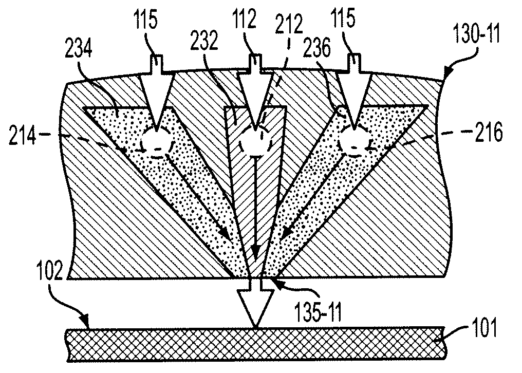
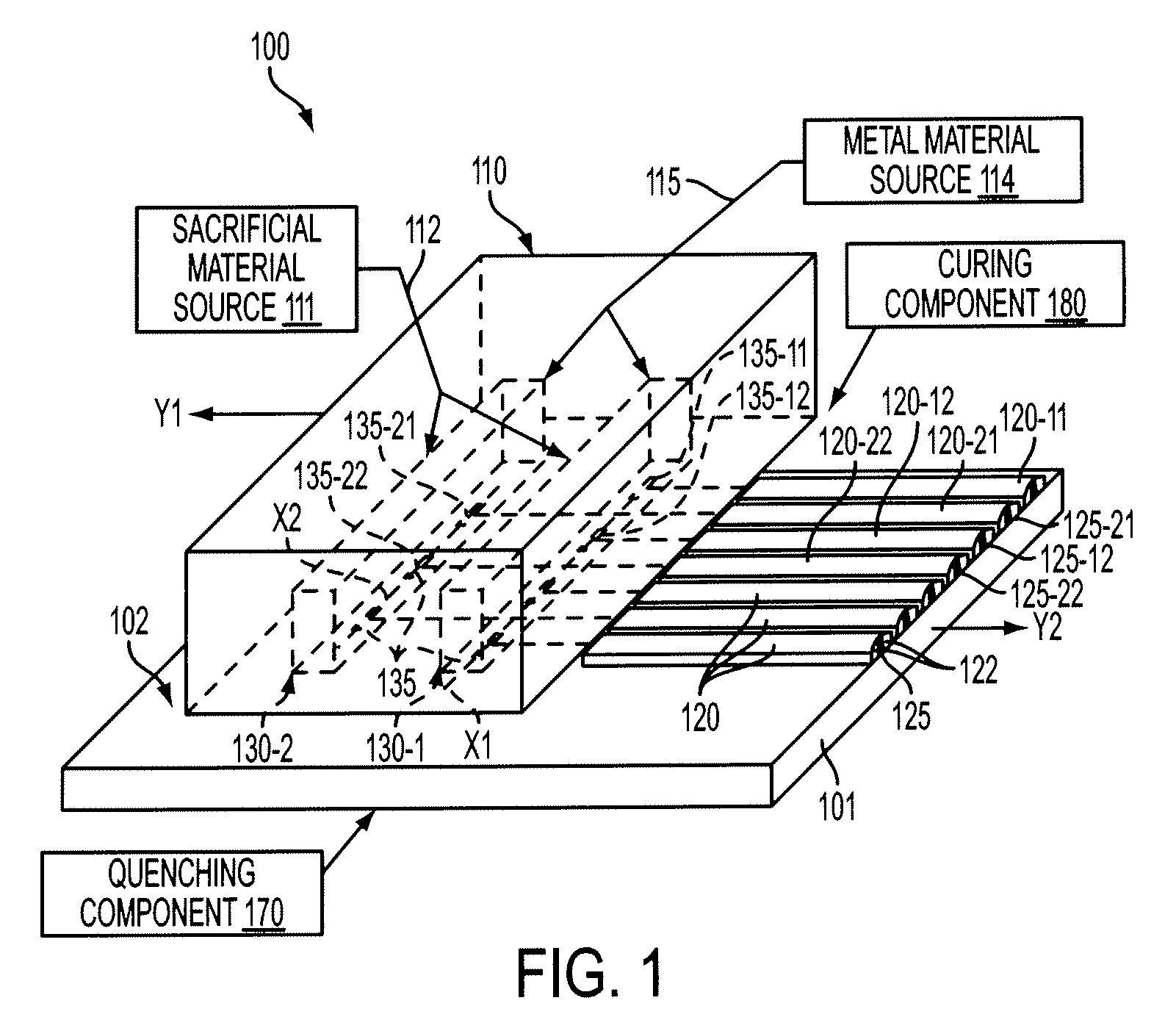
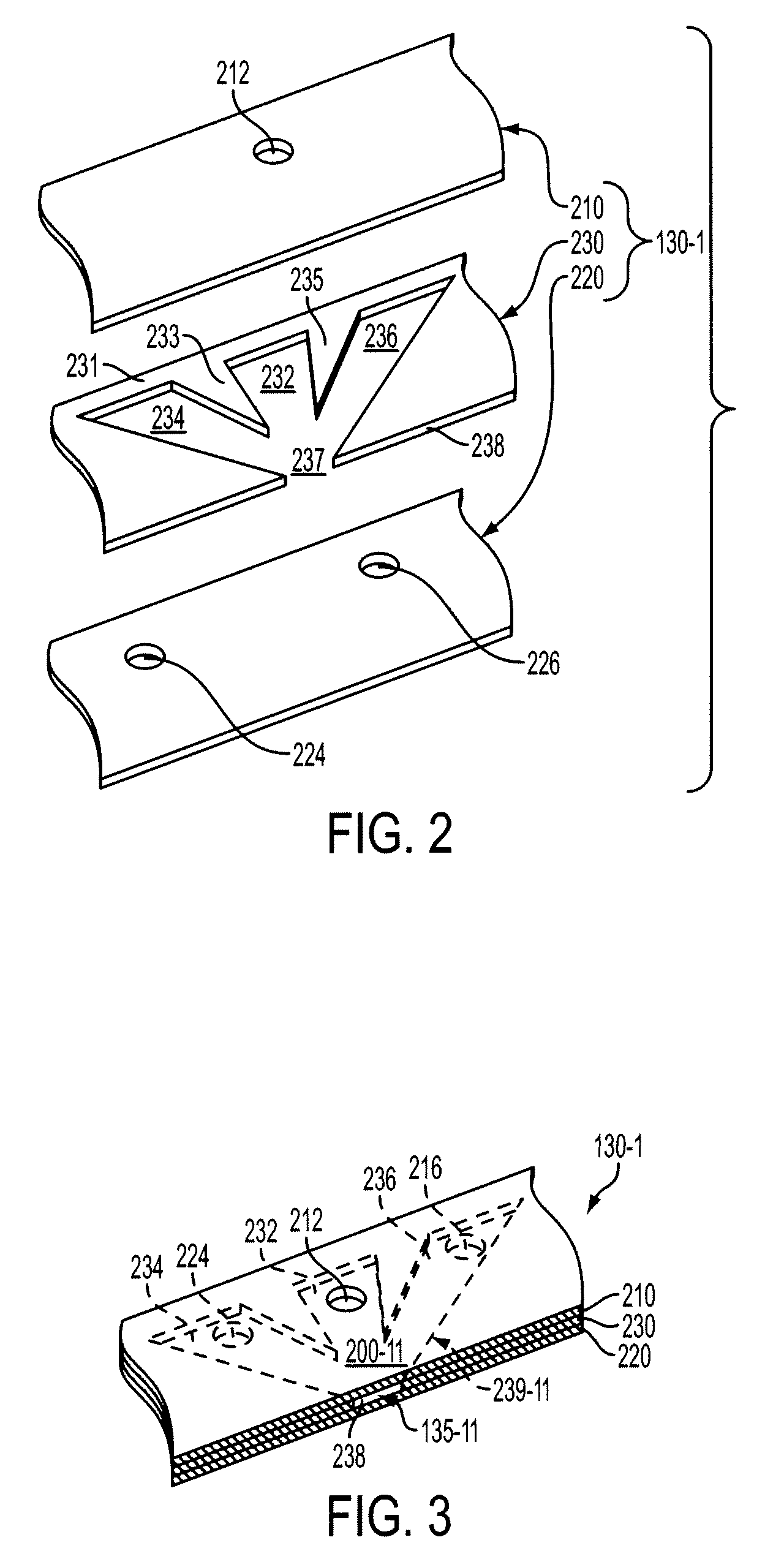
[0022]FIG. 1 illustrates an extrusion apparatus 100 including an extrusion device 110 including two or more co-extrusion heads 130-1 and 130-2 fixedly mounted thereon. Extrusion device 110 is coupled to a first source 111 containing a sacrificial material 112, and a second source 114 containing a gridline material 115. Extrusion heads 130-1 and 130-2 are operably coupled to sources 111 and 114 such that heads 130-1 and 130-2 concurrently apply sacrificial material 112 and a gridline material 115 onto the upper surface 102 of a substrate 101. The materials are applied through pushing and / or drawing techniques (e.g., hot and cold) in which the materials are pushed (e.g., squeezed, etc.) and / or drawn (e.g., via a vacuum, etc.) through extrusion device 110 and / or co-extrusion heads 130-1 and 130-2, and out one or more outlet orifices (exit ports) 135 that are respectively defined in a lower portion of co-extrusion heads 130-1 and 130-2.

[0023]In accordance with an aspect of the invention...


PUM

PropertyMeasurementUnit
Ratioaaaaaaaaaa
Electrical conductoraaaaaaaaaa
Aspect ratioaaaaaaaaaa

Abstract

Closely spaced, high aspect-ratio gridline structures are formed on the surface of a substrate using two or more co-extrusion heads that co-extrude gridline material and sacrificial material such that the deposited gridline material is compressed between opposing portions of the sacrificial material. The co-extrusion heads include three-channel cavity structures that converge to a relatively small outlet orifice that dispenses the gridline material with relatively fine features and a relatively high aspect ratio. The outlet orifices of the co-extrusion heads are disposed in a staggered arrangement such that gridlines extruded from the first co-extrusion head are disposed between two gridlines extruded from the second co-extrusion head. Photovoltaic cells are produced with metal gridlines formed in this manner.

Description

FIELD OF THE INVENTION[0001]The present invention is related to extrusion systems and methods, and more particularly to micro extrusion systems and methods for co-extruding multiple similar and / or dissimilar materials to form relatively fine structures with relatively high aspect ratios.BACKGROUND[0002]With traditional extrusion a billet of material is pushed and / or drawn through a die to create a rod, rail, pipe, etc. Various applications leverage this capability. For instance, extrusion can be used with food processing applications to create pasta, cereal, snacks, etc., pipe pastry filling (e.g., meringue), pattern cookie dough on a cookie pan, generate pastry flowers and borders on cakes, etc. In another application, extrusion can be used with consumer goods, for example, to merge different colored toothpastes together on a toothbrush.[0003]Conventional extrusion techniques are limited, for example, in that they cannot render relatively high aspect-ratio (e.g., 2:1 or greater) fi...

Claims


Application Information

Patent Timeline
IPC IPC(8): H01L21/00B29C48/05B29C48/12
CPCB29C47/0021B29C47/0023B29C47/0052B29C47/062B29C47/065Y10T29/5313H01L31/022425H01M14/005Y02E10/50Y10T29/532B29C47/145B29C48/08B29C48/09B29C48/0016B29C48/19B29C48/21B29C48/307B29C48/05B29C48/12H01J9/20H01J11/20
Inventor FORK, DAVID K.ZIMMERMANN, THOMAS S.
Owner SOLARWORLD IND GMBH
Why Eureka
Try Eureka