Insulated concrete form

Inactive Publication Date: 2008-05-08
SYNTHEON
View PDF59 Cites 11 Cited by
  • Summary
  • Abstract
  • Description
  • Claims
  • Application Information

AI Technical Summary

Benefits of technology

[0024]FIG. 6 is a cut away perspective view of an insula

Problems solved by technology

This prior art technique has drawbacks.
Formation of the concrete walls is inefficient because of the time required to erect the forms, wait until the concrete cures, and take down the forms.
This prior art technique, therefore, is an expensive, labor-intensive process.
Although the prior art includes many proposed variations to achieve improvements with this technique, drawbacks still exist for each design.
The large amount of horizontal and vertical joints that require bracing to correctly position the blocks during a concrete pour, restricts their use to shorter wall lengths and lower wall heights.
Plaster finishing crews have difficulty hanging drywall on such systems due to the problem of locating molded in furring strips.

Method used


Image

  • Insulated concrete form
  • Insulated concrete form
  • Insulated concrete form

Examples


Embodiment Construction

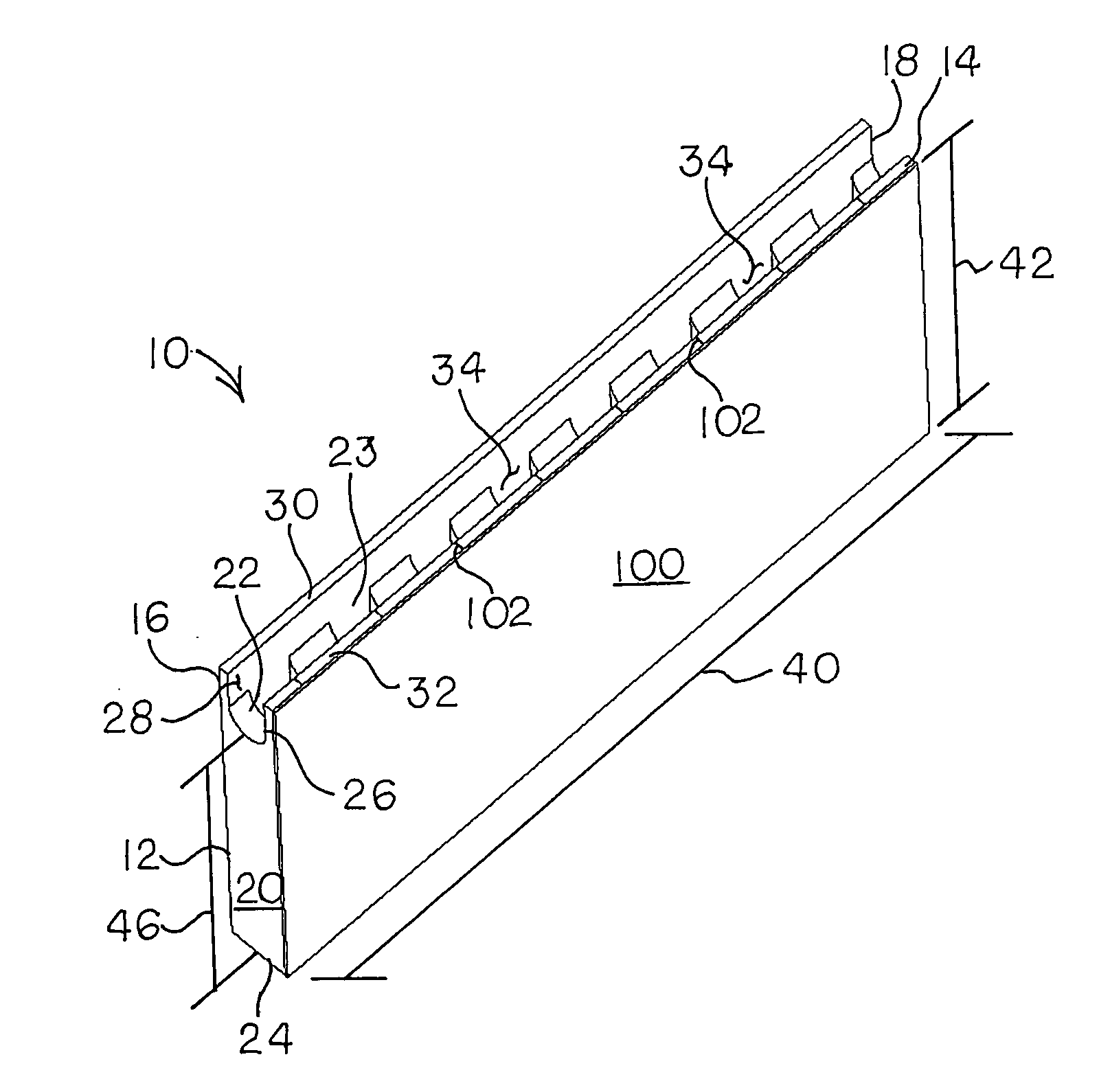
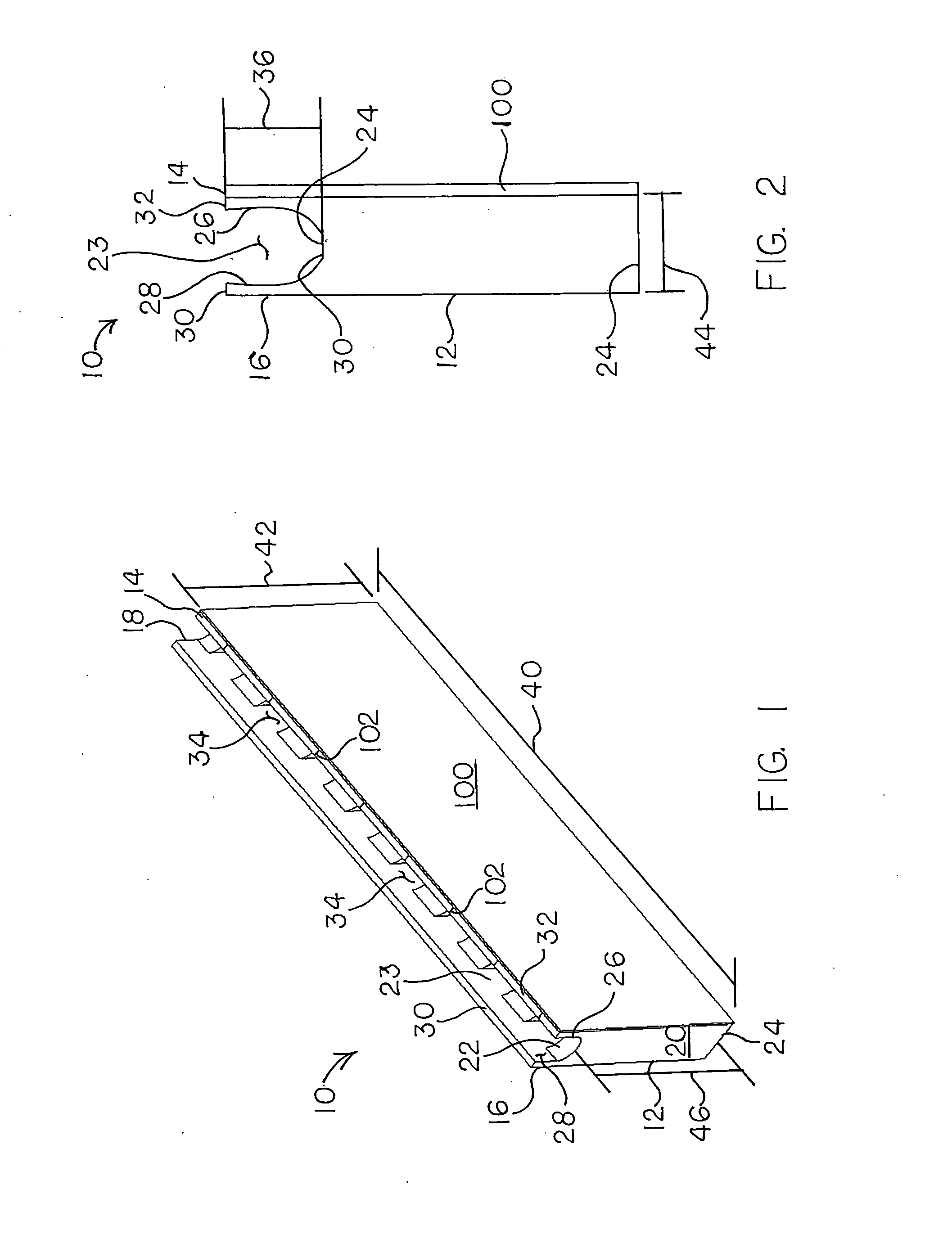
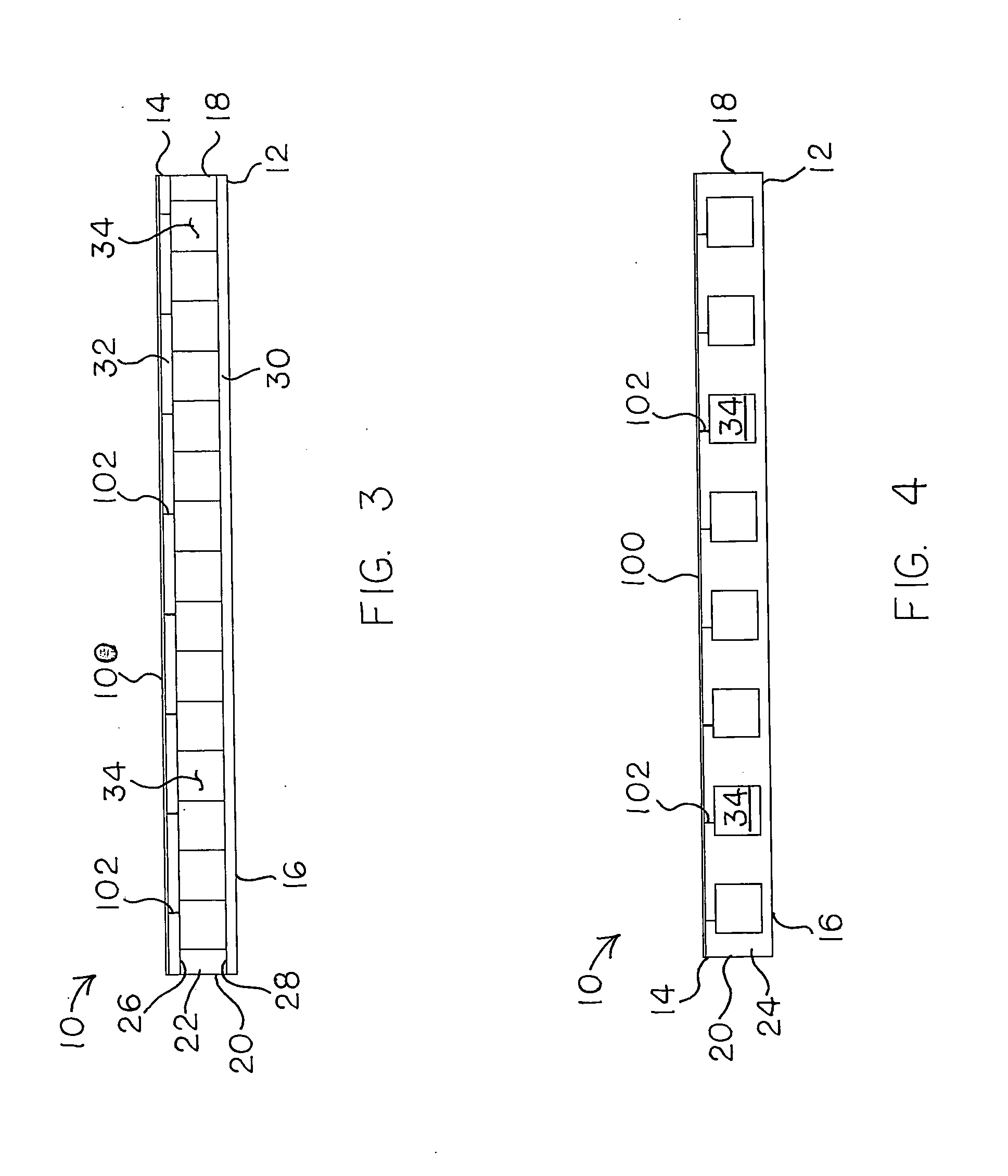
[0028]For the purpose of the description hereinafter, the terms “upper”, “lower”, “inner”, “outer”, “right”, “left”, “vertical”, “horizontal”, “top”, “bottom”, and derivatives thereof, shall relate to the invention as oriented in the drawing Figures. However, it is to be understood that the invention may assume alternate variations and step sequences except where expressly specified to the contrary. It is also to be understood that the specific devices and processes, illustrated in the attached drawings and described in the following specification, is an exemplary embodiment of the present invention. Hence, specific dimensions and other physical characteristics related to the embodiment disclosed herein are not to be considered as limiting the invention. In describing the embodiments of the present invention, reference will be made herein to the drawings in which like numerals refer to like features of the invention.

[0029]Other than where otherwise indicated, all numbers or expressi...


PUM

PropertyMeasurementUnit
Lengthaaaaaaaaaa
Lengthaaaaaaaaaa
Lengthaaaaaaaaaa

Abstract

A concrete wall forming system including a plurality of mold units for forming a wall of concrete. The mold units include a bond beam form extending into the body lengthwise, defined by a first wall, a second wall, a bond beam form bottom, a first end and a second end where the first wall and second wall extend a depth defined by a portion of the distance from the top surface to the bottom surface and where the bond beam form does not touch the first side or the second side. First and second ledges extend lengthwise along the body from the first and second sides respectively to the first and second walls respectively of the bond beam form. The bond beam form bottom extends from the first wall to the second wall. At least two column forms extend from the bond beam form bottom to a bottom surface.

Description

BACKGROUND OF THE INVENTION[0001]1. Field of the Invention[0002]The present invention is directed to a concrete wall forming system and insulated concrete walls formed using the wall forming system.[0003]2. Description of the Prior Art[0004]Concrete walls in building construction are most often produced by first setting up two parallel form walls and pouring concrete into the space between the forms. After the concrete hardens, the builder then removes the forms, leaving the cured concrete wall.[0005]This prior art technique has drawbacks. Formation of the concrete walls is inefficient because of the time required to erect the forms, wait until the concrete cures, and take down the forms. This prior art technique, therefore, is an expensive, labor-intensive process.[0006]Accordingly, techniques have developed for forming modular concrete walls, which use a foam insulating material. The modular form walls are set up parallel to each other and connecting components hold the two form w...

Claims


Application Information

Patent Timeline
IPC IPC(8): E04B2/86B28B7/34E04C2/10E04C1/40
CPCE04B2/8629E04C2/205E04C1/40E04B2002/867
Inventor AU, GINAWATIJARVIE, SHAWN P.RUBB, JUSTIN D.WILLIAMS, MICHAEL T.ARAOS, DANIELHILEMAN, BLAIN
Owner SYNTHEON
Why Eureka
Try Eureka