Combustor dome panel heat shield cooling

a technology of heat shield cooling and dome panel, which is applied in the direction of machines/engines, mechanical equipment, light and heating apparatus, etc., can solve the problems of deteriorating cooling effectiveness, high thermal gradient, and additional damage, and achieve the effect of reducing interferen

Active Publication Date: 2008-05-08
PRATT & WHITNEY CANADA CORP
View PDF4 Cites 56 Cited by
  • Summary
  • Abstract
  • Description
  • Claims
  • Application Information

AI Technical Summary

Benefits of technology

[0007]In a third aspect, provided is a method of cooling a gas turbine combustor heat shield: comprising directing a first jet of cooling air through a combustor wall and generally normally upon a surface of a peripheral lip of...

Problems solved by technology

These lips are exposed to high gas temperature relative to the remainder of an otherwise well-cooled heat shield, resulting in high thermal gradients.
The thermal gradient inevitab...

Method used


Image

  • Combustor dome panel heat shield cooling
  • Combustor dome panel heat shield cooling
  • Combustor dome panel heat shield cooling

Examples


Embodiment Construction

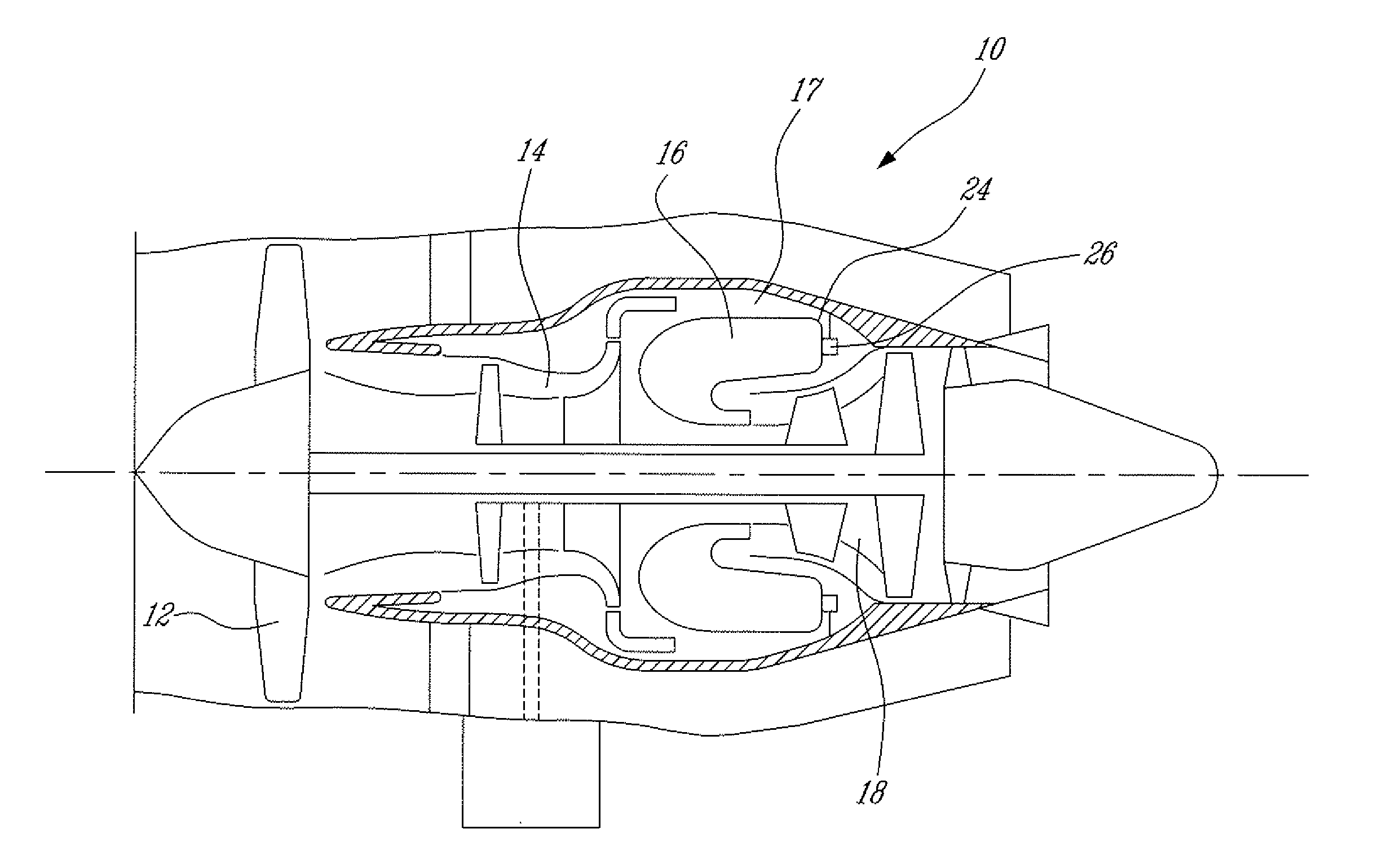
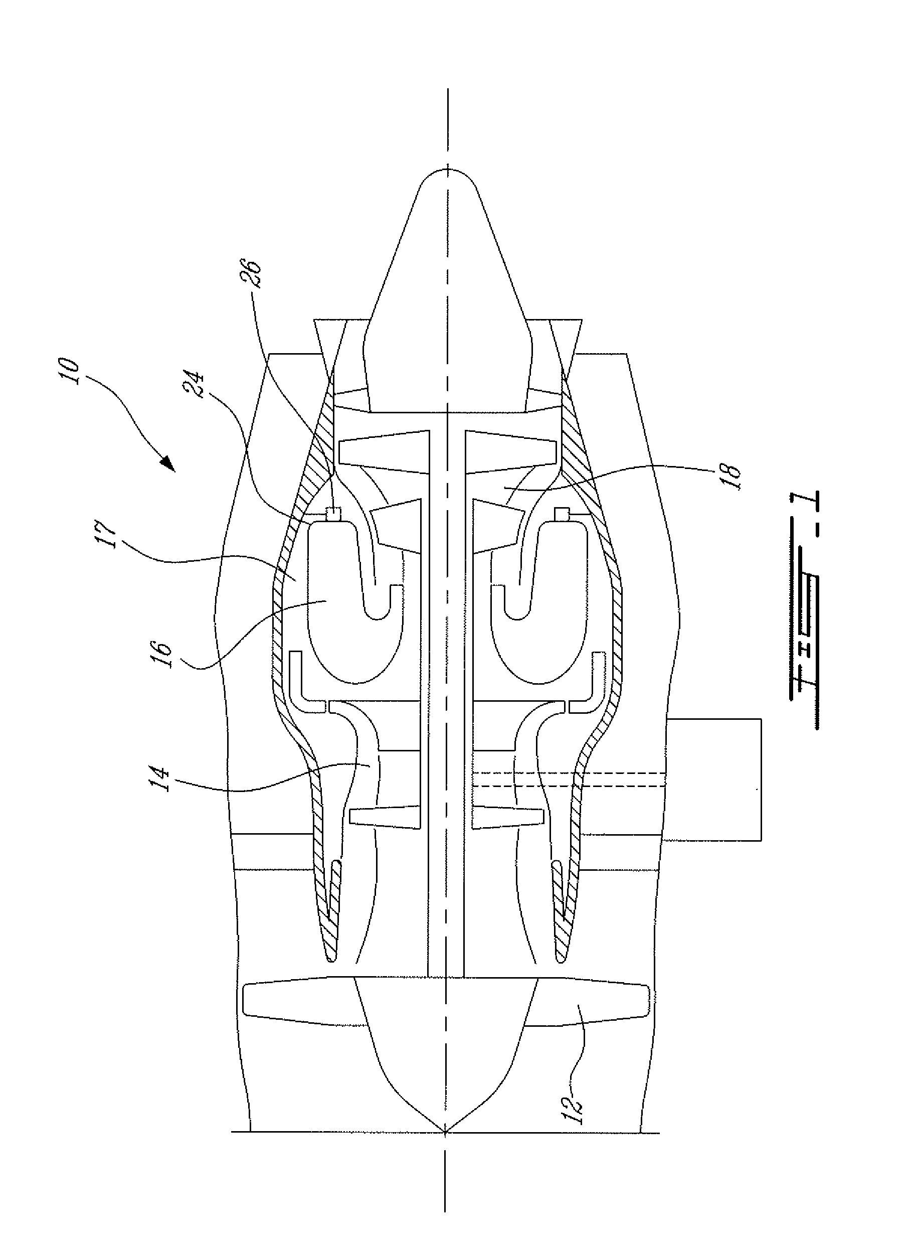
[0015]FIG. 1 illustrates a gas turbine engine 10 of a type preferably provided for use in subsonic flight, generally comprising in serial flow communication a fan 12 through which ambient air is propelled, a multistage compressor 14 for pressurizing the air, a combustor 16 in which the compressed air is mixed with fuel and ignited for generating an annular stream of hot combustion gases, and a turbine section 18 for extracting energy from the combustion gases.

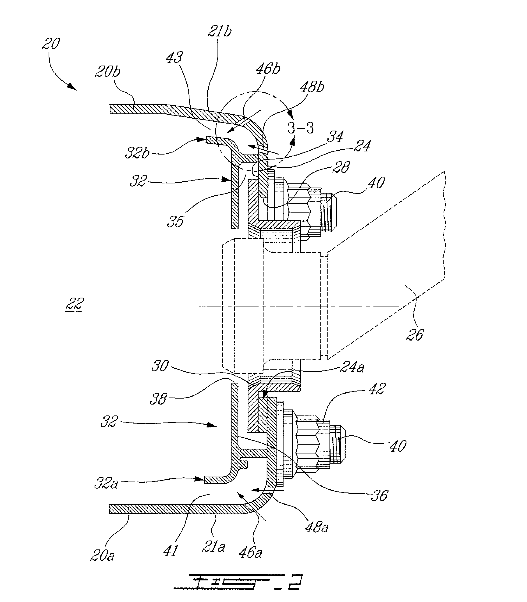
[0016]The combustor 16 is housed in a plenum 17 supplied with compressed air from compressor 14. As shown in FIG. 2, the combustor 16 comprises an annular combustor shell 20, typically composed of a radially inner liner 20a and a radially outer liner 20b, each having a wall 21a, 21b respectively, defining a combustion chamber 22. The portion of the combustor illustrated in FIG. 2 is generally referred to as the dome 24 of the combustor 16. The dome 24 typically includes an annular dome panel 24a interposed between the inner and...


PUM


Abstract

A gas turbine engine combustor having a dome heat shield includes a cooling scheme having a plurality of impingement cooling holes extending through the combustor and a plurality of adjacent ejector holes for directing cooling air past the heat shield lips of the dome heat shields. The impingement and ejector holes are preferably staggered to reduce interaction therebetween.

Description

TECHNICAL FIELD[0001]The invention relates generally to gas turbine engine combustors and, more particularly, to combustor heat shield cooling.BACKGROUND OF THE ART[0002]Combustor heat shields provide protection to the dome portion of the combustor shell. The heat shields may be provided with radially inner and radially outer lips. These lips are exposed to high gas temperature relative to the remainder of an otherwise well-cooled heat shield, resulting in high thermal gradients. The thermal gradient inevitably results in cracks due to thermal mechanical fatigue. Cracking in the lips further deteriorates cooling effectiveness and results in additional damage due to high temperature oxidation.[0003]Accordingly, there is a need for an improved cooling scheme while avoiding any detrimental effect on the rest of the heat shield surface cooling.SUMMARY[0004]It is therefore an object of this invention to provide an improved cooling technique.[0005]In one aspect, provided is A combustor co...

Claims


Application Information

Patent Timeline
IPC IPC(8): F02C1/00
CPCF23R3/10F05D2260/201F01D25/12F23R2900/03044F23R3/002
Inventor PATEL, BHAWAN B.MARKARIAN, LORINPARKMAN, KENNETHPHILLIPS, STEPHEN
Owner PRATT & WHITNEY CANADA CORP
Why Eureka
Try Eureka