Strain gauge sensor system and method

a sensor system and train gauge technology, applied in the direction of instruments, apparatus for force/torque/work measurement, roads, etc., can solve the problems of easy breakage, huge financial consequences of any mooring accident, and partial or even total breakage of platforms or vessels

Inactive Publication Date: 2008-05-08
HONEYWELL INT INC
View PDF26 Cites 31 Cited by
  • Summary
  • Abstract
  • Description
  • Claims
  • Application Information

AI Technical Summary

Benefits of technology

[0026]The step of providing the position sensor device can comprise providing at least one first magnetoresistive or Hall Effect sensor.
[0027]The step of providing the trigger sensor device can comprise providing the at least one first magnetoresistive or Hall Effect sensor.

Problems solved by technology

In mooring applications, a loss in structural integrity of such mooring ropes affect the rope performance and can lead to rope failure resulting in partial or even total breakouts of platforms or vessels.
The financial consequences of any mooring accident can be enormous.
Strain accumulation and change along the rope during rope deployment is an essential key factor in rope failure.
However, it suffers from easy breakage and requires using a complicated winding method and high source optical power into the fiber.
However, this latter method suffers from short measurement range of rope (up to 1 km), long gauge length (10 m), poor strain measurement resolution (less than 1% over 1 m gauge), poor elongation measurement range (up to 7%) and requires the use of a special process to add the reflective interfaces between the gauge length of the rope.

Method used


Image

  • Strain gauge sensor system and method
  • Strain gauge sensor system and method
  • Strain gauge sensor system and method

Examples


Embodiment Construction

[0040]The particular values and configurations discussed in these non-limiting examples can be varied and are cited merely to illustrate at least one embodiment of the present invention and are not intended to limit the scope of the invention.

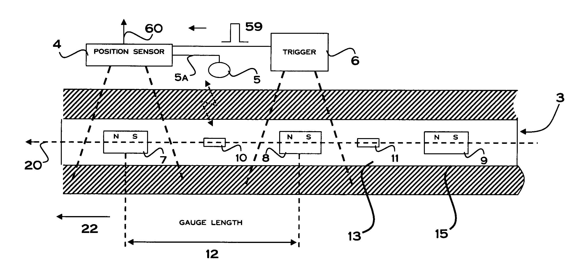
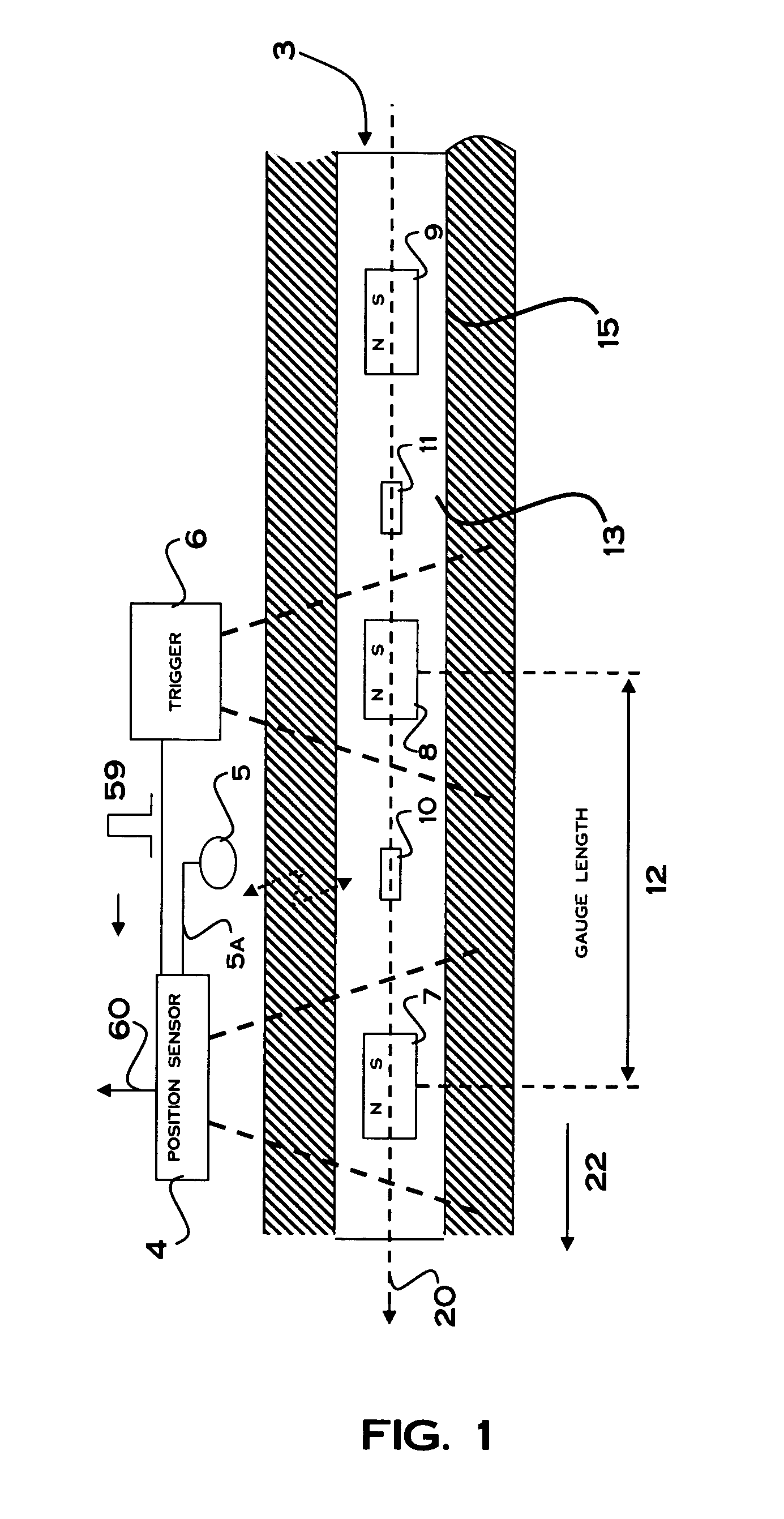
[0041]Referring to FIG. 1 of the accompanying drawings, which illustrates schematic of a strain gauge sensor system for measuring strain in a line according to one embodiment, the sensor system 1 has a sensor target assembly 3 carried on a line 2 and includes magnets 7, 8, 9 spaced apart by gauge lengths 12 along the line 2. System 1 also includes first and second sensor devices 6, 4 for sensing the magnetic fields of the magnets 7, 8, 9.

[0042]The strain gauge sensor system can be applied in a number of different applications, such as, for example, mooring line deployment systems. The system 1 of the illustrative embodiment of the accompanying drawings is adapted for use in marine mooring applications in which the line is a high performance fib...


PUM

PropertyMeasurementUnit
elongationaaaaaaaaaa
gauge lengthaaaaaaaaaa
elongationaaaaaaaaaa

Abstract

A strain gauge sensor system and method for measuring the strain in a member, such as a fiber rope, has a sensor target assembly having a plurality of magnets carried spaced apart by individual gauge lengths along the member. Position and trigger sensor devices are configured spaced apart along side a desired path of travel of the member. When the member is fed along the desired path of travel, the trigger sensor device, in response to magnetically sensing a passing magnet, triggers the position sensor device to read the position of an adjacent passing magnet. The strain in the gauge length is determined from the read position. RFID tags placed on the member between the magnets can be identified by an RF reader to identify a particular gauge length being measured. The system can include a deployment device for feeding the member along the desired path.

Description

[0001]Embodiments are generally related to sensor methods and systems. Embodiments are also related to strain gauge sensor methods and systems for measuring the strain in a member, in particular, a member such as line. Embodiments are also related to magnetoresistive sensing devices. Also, embodiments are related to strain gauge sensor methods and systems for measuring strain in mooring lines, such as fiber ropes.BACKGROUND OF THE INVENTION[0002]High performance fiber ropes and other types of lines are used in a variety of industrial applications such as mooring deep-water drilling and production platforms. Honeywell Spectra® fiber rope, a kind of synthetic fiber rope constructed from high performance polymers, is widely used in civil, military and off-shore industries. The synthetic fiber ropes have high strength-to-weight ratios and possess adequate stiffness.[0003]In mooring applications, a loss in structural integrity of such mooring ropes affect the rope performance and can lea...

Claims


Application Information

Patent Timeline
Patent Type & Authority Applications(United States)
IPC IPC(8): G01L1/12
CPCG01L1/122D07B1/145
Inventor TURNBULL, FRANKZHANG, WENWEI
Owner HONEYWELL INT INC
Why Eureka
Try Eureka