Gas identification system and respiratory technologies volumetrically corrected gas delivery system

a gas delivery system and gas identification technology, applied in the field of patient ventilation system, can solve the problems of life-threatening events, inaccurate adjustment when the gas composition is altered, and helium itself has no curative value and cannot support li

Active Publication Date: 2008-05-08
VYAIRE MEDICAL 202 INC
View PDF64 Cites 12 Cited by
  • Summary
  • Abstract
  • Description
  • Claims
  • Application Information

AI Technical Summary

Benefits of technology

[0010] The present invention provides an automatic electronic gas identification ID, which preferably comprises a gas inlet and a voltage divider attached on the gas inlet of the ventilator. The gas inlet interlocks a gas source such as a conventional gas bottle or tank with the gas delivery system. When the gas is supplied to the gas delivery system, the voltage divider is inserted, i.e., plugged in to the ventilator. The voltage divider includes a resistor, across which a voltage drop is measured to identify the actual gas composition supplied to the gas delivery system. A lookup table in which a list of voltage drop values corresponding to the various gases used in ventilation therapy is stored is further included. Once the voltage drop is measured, the corresponding gas is determined from the lookup table to provide an automatic fail-safe identification of the actual gas composition supplied to the ventilator.

Problems solved by technology

That is, helium itself has no curative value and cannot support life.
However, such adjustment may be inaccurate when the gas composition is altered.
In addition to obtaining an ineffective ventilation, such inaccuracy may cause a life threatening event, especially when a patient is in critical condition.
This again suppresses the desired oxygen delivery effectiveness of the ventilation system.
When the patient is under a critical condition, such delivery ineffectiveness and / or inaccuracy may endanger the patient.

Method used


Image

  • Gas identification system and respiratory technologies volumetrically corrected gas delivery system
  • Gas identification system and respiratory technologies volumetrically corrected gas delivery system
  • Gas identification system and respiratory technologies volumetrically corrected gas delivery system

Examples


Embodiment Construction

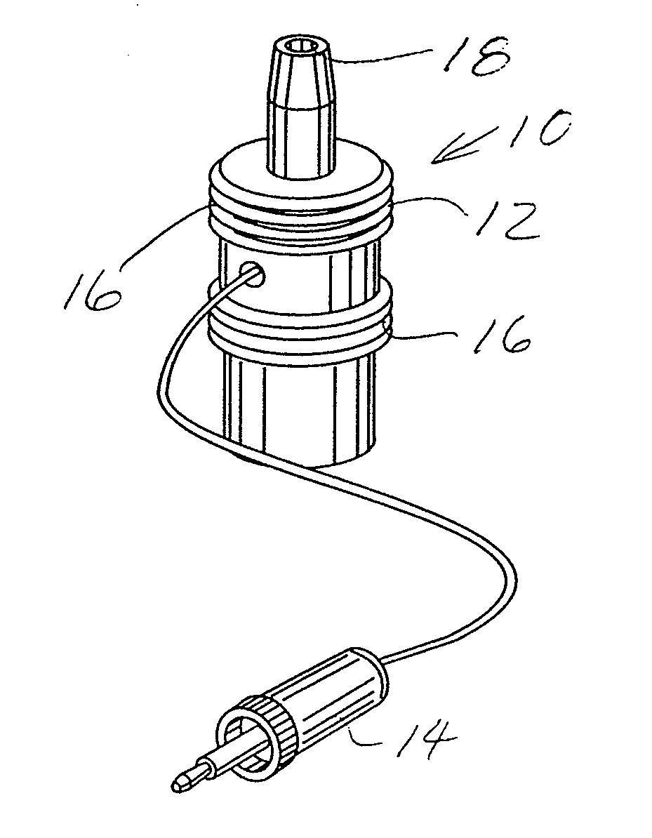
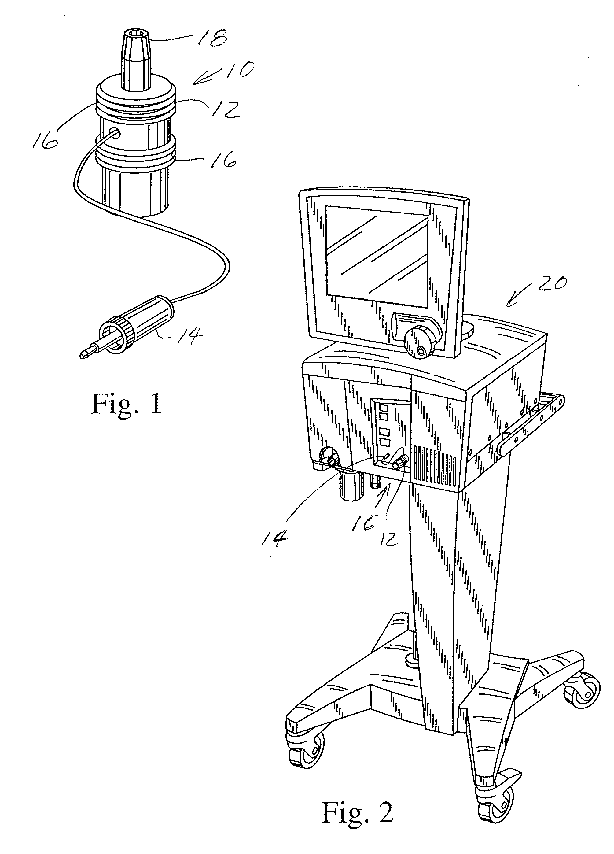
[0022]FIG. 1 shows a perspective view of a gas identifier 10 provided by the present invention. As shown in FIG. 1, the gas identifier 10 comprises a gas inlet 12 and a voltage divider 14 adapted to provide a pneumatic and electrical interface to the gas delivery system, i.e., ventilator 20 of the present invention. The gas inlet 12 interlocks to a conventional gas source such as a gas tank (not shown) and with the gas delivery system ventilator 20 as shown in FIG. 2. As is well known, conventional gas tanks providing different gas sources are supplied with standardized pneumatic connection terminals formed in conformity with either United States and / or European standards having differing thread and / or diameter sizes which uniquely identify the particular gas composition of the gas supply. The threads 16 or thread diameter on one end of the gas inlet 12 can be made in differing sizes to match the standardized size and configuration for the standardized pneumatic connection terminal....


PUM


Abstract

A gas delivery system, having a gas identification, by which a gas supplied to the gas delivery system is identified, a blender, blending oxygen and the gas to provide a gas mixture with an oxygen flow rate set up by an operator, and at least one flow sensor, to measure a flow rate of the gas mixture. The blender is driven by an actuator motor to various blender positions with the blender positions being calibrated based on the specific heat ratio and the gas constant of the gas. The flow sensor can be installed at the inspiratory circuit, the proximal circuit and the expiratory circuit of the gas delivery system. The flow sensor output is corrected based on the actual conditions, including the temperature, pressure and humidity, and characteristics of the gas mixture.

Description

CROSS-REFERENCE TO RELATED APPLICATIONS [0001] (Not Applicable) STATEMENT RE: FEDERALLY SPONSORED RESEARCH / DEVELOPMENT [0002] (Not Applicable) BACKGROUND OF THE INVENTION [0003] The present invention relates generally to a patient ventilation system, and more particularly, to a gas identification (ID) and a volumetrically corrected gas delivery system applied to a ventilation system. [0004] Ventilation treatments have been used as a therapeutic intervention to relieve dyspnea for a patient in acute respiratory distress directly related to severe increases in airway resistance. For moving gas into and out of the lungs, an open airway for the gas to flow from the higher pressure zone to the lower pressure zone is required. The greater the pressure between two points of the airway, the greater volume of gas is moved within the airway. The pressure in airway is directly related to the dynamic pressure gradient during the respiratory cycle, the flow rate of the gas, the density and visco...

Claims


Application Information

Patent Timeline
Patent Type & Authority Applications(United States)
IPC IPC(8): A61M16/12A61M16/00A61M16/10
CPCA61M2016/0042A61M2016/0039A61M2202/025A61M2205/702A61M2016/102A61M2016/0036A61M16/12A61M16/0833A61M16/0003A61M16/1005A61M16/122A61M16/201A61M16/0066A61M16/06A61M2016/0027A61M2016/003A61M2016/1025A61M2205/3334A61M2205/3368A61M2205/50A61M2205/70
Inventor DE SILVA, ADRIAN D.GLUKHOV, SAMUEL A.
Owner VYAIRE MEDICAL 202 INC
Why Eureka
Try Eureka