Ceramic filter
a ceramic filter and ceramic technology, applied in the field of ceramic filters, can solve the problems of difficult uniform film formation, deterioration of selectivity for separating a mixture, and thick carbon membranes, so as to improve the transmission amount of the target to be separated and prevent the increase of pressure loss at the base material portion.
Inactive Publication Date: 2008-05-08
NGK INSULATORS LTD
View PDF0 Cites 28 Cited by
- Summary
- Abstract
- Description
- Claims
- Application Information
AI Technical Summary
Benefits of technology
[0005] However, in a case where a carbon membrane is formed on a porous base material, since a carbon membrane precursor is dipped in the base material, it is difficult to form a uniform film. Therefore, the film is not uniformly formed, and hence selectivity for separating a mixture deteriorates. When the precursor is dipped to form the carbon membrane, the carbon membrane tends to be formed to be thick, and flux (transmission flux) deteriorates. Furthermore, in a method in which the surface of the porous base material is impregnated with a silica sol to form the carbon membrane on the surface as in Patent Document 1, pore diameters of the carbon membrane increase owing to the formation of the sol layer, and hence a separation performance improves with respect to a part of gases, for example, C3H8 / C3H6 or the like having molecule diameters of 0.43 nm or more and a comparatively large molecular weight. However, in another industrially useful mixture having a comparatively small molecular weight, for example, CO2 / CH4, N2 / O2, water / EtOH or the like, the selectivity deteriorates, the flux also lowers owing to an influence of pressure loss due to the silica sol, and the separation performance remains to be low as compared with a method of directly forming the carbon membrane on the porous base material.
[0006] An objective of the present invention is to provide a ceramic filter formed on a porous base material and having satisfactory transmission amount and selectivity.
[0014] In the ceramic filter of the present invention, since the ceramic surface deposited layer consisting of the ceramic porous body having the average particle diameter smaller than that of the ceramic porous body constituting the base material main body is formed on the surface of the base material main body consisting of the ceramic porous body and the carbon membrane layer is formed on the ceramic surface deposited layer, increase of pressure loss at a base material portion can be prevented, and a transmission amount of a target to be separated can be improved. Moreover, since the carbon membrane layer is formed on the ceramic surface deposited layer or the heterogeneous surface deposited layer having a small average particle diameter, penetration of a film precursor resin constituting the carbon membrane layer to a base material can be inhibited. Therefore, an amount of a film precursor resin solution to be used decreases, and the carbon membrane layer can thinly and uniformly be formed on the base material.
Problems solved by technology
However, in a case where a carbon membrane is formed on a porous base material, since a carbon membrane precursor is dipped in the base material, it is difficult to form a uniform film.
Therefore, the film is not uniformly formed, and hence selectivity for separating a mixture deteriorates.
When the precursor is dipped to form the carbon membrane, the carbon membrane tends to be formed to be thick, and flux (transmission flux) deteriorates.
However, in another industrially useful mixture having a comparatively small molecular weight, for example, CO2 / CH4, N2 / O2, water / EtOH or the like, the selectivity deteriorates, the flux also lowers owing to an influence of pressure loss due to the silica sol, and the separation performance remains to be low as compared with a method of directly forming the carbon membrane on the porous base material.
Method used
View moreImage
Smart ImageViewing Examples

Examples
examples
[0030] The present invention will hereinafter be described in more detail based on examples, but the present invention is not limited to these examples.
Login to View More PUM
| Property | Measurement | Unit |
|---|---|---|
| Length | aaaaa | aaaaa |
| Length | aaaaa | aaaaa |
| Length | aaaaa | aaaaa |
Abstract
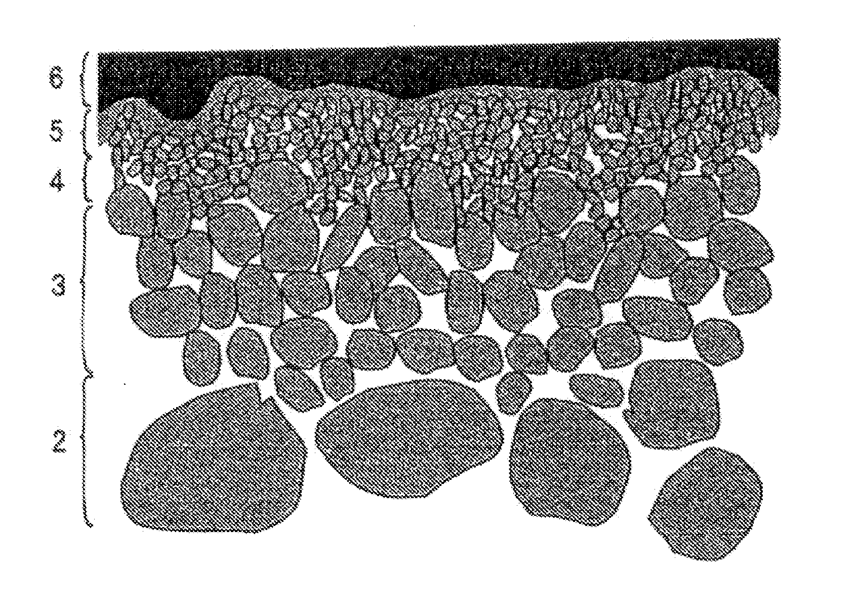
There is provided a ceramic filter formed on a porous base material and having satisfactory transmission amount and selectivity. The ceramic filter has a first surface dense layer 3 having an average pore diameter of 0.1 to 3 μm on an alumina porous base material 2 having an average pore diameter of 1 to 30 μm, a second surface dense layer 4 having an average pore diameter of 0.01 to 0.5 μm on the first surface dense layer 3, and a third surface dense layer 5 made of a titania sol and having an average pore diameter of 0.3 to 20 nm on the second surface dense layer 4. Moreover, on the third surface dense layer 5, a carbon membrane layer 6 as a molecular sieve carbon membrane is formed.
Description
TECHNICAL FIELD [0001] The present invention relates to a ceramic filter for use in separation of various mixtures. BACKGROUND ART [0002] From viewpoints of environment and energy saving, development of a separation membrane for filtering and separating a specific gas or the like from a mixture of various gases or the like has been advanced. As such a separation membrane, a polymer film such as a polysulfone film, a silicon film, a polyamide film or a polyimide film or the like is known, but there are problems of thermal resistance and chemical resistance, for example, a problem that when the mixture includes an organic solvent, the film is degraded and deteriorated. [0003] On the other hand, examples of the separation membrane having excellent thermal resistance and chemical stability include a carbon membrane, and a separation membrane including the carbon membrane formed on a porous base material is known. For example, Patent Document 1 discloses a molecular sieve carbon membrane...
Claims
Login to View More Application Information
Patent Timeline
 IPC IPC(8): B01D24/00
CPCB01D63/066B01D67/0067B01D69/12B01D71/021C04B35/10C04B35/52B01D2325/20C04B2111/00405C04B2111/00801C04B38/0032B01D2325/022B01D2325/02B01D2325/0283B01D2325/0233
Inventor ICHIKAWA, AKIMASATOMITA, TOSHIHIRO
Owner NGK INSULATORS LTD