Apparatus for concentrating and diluting specific gas and method for concentrating and diluting specific gas

a technology of specific gas and apparatus, which is applied in the direction of liquid degasification, lighting and heating apparatus, separation processes, etc., can solve the problems of increased apparatus cost, increased apparatus size, explosion danger, etc., and achieves improved process efficiency, small size, and improved effect

Active Publication Date: 2010-07-01
TOSHIBA MITSUBISHI-ELECTRIC IND SYST CORP
View PDF2 Cites 387 Cited by
  • Summary
  • Abstract
  • Description
  • Claims
  • Application Information

AI Technical Summary

Benefits of technology

[0030]According to the first aspect of the invention, only a specific gas can be continuously separated into a diluted gas and a concentrated gas with only one step, whereby such an advantage can be obtained that provides an apparatus for concentrating and diluting a specific gas that is improved in process efficiency, has a small size, is inexpensive, and has safety, as compared to the conventional art, and provides a method for concentrating and diluting a specific gas therefor.
[0031]According to the second aspect of the invention, a chamber having filled therein a particle material for condensation and vaporization selectively condensing the specific gas or having equipped therein a gas transmission member selectively transmitting other gases than the specific gas is cooled, so as to cool a gas containing plural gas species fed to the chamber, and by the cooling effect of the gas, the adsorption rate of the specific gas is improved to improve the effect of selectively condensing the specific gas on the particle material for condensation and vaporization. The invention also has an advantage of further improving the effect of selectively transmitting the other gases than the specific gas through the gas transmission material by cooling the gas.
[0032]According to the apparatus for concentrating and diluting a specific gas containing the chamber having equipped therein the particle material of the invention, a means for continuously retrieving the concentrated gas of the specific gas from a gas retrieving pipe through the automatic pressure controller (APC) having a flow rate controlling means automatically controlling the pressure of the chamber is provided, and the diluted gas of the specific gas is continuously retrieved from a gas retrieving pipe through a flow rate controller having a means capable of controlling the flow rate with amass flow rate controller or a flow rate valve provided on an upper part of the chamber, whereby the concentration of the diluted gas and the flow rate and the concentration of the concentrated gas of the specific gas can be controlled by setting the flow rate of the diluted gas of the specific gas, and a stable concentrated gas can be retrieved.
[0033]According to the apparatus for concentrating and diluting a specific gas containing the chamber having equipped therein the gas transmission member of the invention, an automatic pressure controller I (APC I) or a gas pressure controlling valve I controlling the inner pressure P1 of the chamber of the diluted gas having the specific gas removed by transmitting other gases than the specific gas at the diluted gas retrieving part of the chamber is provided, an automatic pressure controller II (APC II) or a gas pressure controlling valve II controlling an inner pressure P2 at the concentrated gas retrieving part of the chamber is provided, and a gas pressure difference ΔP (=P2−P1) between the diluted gas retrieving part and the concentrated gas retrieving part is provided, whereby the transmission amount of the gas other than the specific gas can be increased to separate the gas to a higher concentration, and a stable concentrated gas can be retrieved.
[0034]According to the apparatus for concentrating and diluting a specific gas containing the chamber having equipped therein the gas transmission member of the invention, the inner pressure P1 in the chamber at the retrieving part of the diluted gas having the specific gas removed by transmitting the other gases than the specific gas is set to the atmospheric pressure (0 MPa) or more, and the pressure P2 at the concentrated gas retrieving part is set to a range of from 0.1 MPa to 0.5 MPa, to provide a gas pressure difference ΔP (=P2−P1) between sides of the gas transmission members of 0.1 MPa or more, whereby the diluted gas can be released without necessity of decreasing the pressure at the diluted gas retrieving part below the atmospheric pressure to separate the gas to a higher concentration, and a stable concentrated gas can be retrieved.
[0035]According to the apparatus for concentrating and diluting a specific gas containing the chamber having equipped therein the gas transmission member of the invention, an ozonized gas containing an ozone gas is used as the gas containing plural gas species that is fed to the concentrating and diluting apparatus, and the gas transmission member is constituted with a Teflon (a trade name) membrane material or a ceramic material, whereby the gas transmission member can have ozone resistance or NOx resistance to provide an advantage of providing a stable concentrating and diluting apparatus having a longer service life.

Problems solved by technology

Furthermore, no document discloses such an apparatus and method that the upper part of the chamber is cooled with a cooler to condense selectively a specific gas on the surface of the particle material, and other gases than the specific gas are selectively transmitted through the gas transmission member (membrane), and the condensed gas is vaporized on the surface of the heated particle material or gas transmission member (membrane) on the lower part of the chamber, whereby the specific gas is concentrated.
In the concentrating apparatus, the system becomes complicated since the operations of the three steps are repeated alternately, and control in pressure and flow rate and control of valves for switching the pipings for every steps become complicated, whereby such a problem arises that the apparatus is increased in size, and the cost of the apparatus is increased.
Upon vaporizing the liquefied ozone liquid or adsorbed ozone by heating, if they are rapidly heated, abrupt vaporization or desorption occurs from the ozone liquid or adsorbed ozone to cause danger of explosion due to rapid increase of the gas pressure.
Accordingly, since the rapid vaporization or desorption is prevented from occurring, and the vaporization or desorption is to be effected in a low pressure state, there is such a problem that only an ozonized gas having a low pressure can be supplied, and there are such problems that in the field of production of semiconductors, mass production (batch process) cannot be attained, and a concentrated ozone gas cannot be dispersed uniformly to a wafer processing chamber.
Furthermore, an ozone gas generated with an ozone generator is continuously fed to a liquefaction chamber or an adsorption chamber to liquefy the gas to a prescribed amount or to adsorb once the gas the adsorbent to around 100% ozone, and the gas that cannot be liquefied or the ozone gas that cannot be adsorbed is discarded to a waste ozone apparatus, which brings about such a problem that an ozone gas cannot be effectively concentrated.
In the conventional technique of removing a NOx or CO2 gas as a specific gas to clean a waste gas or air in a room (dilution of a specific gas), when the adsorption amount of the adsorbent is saturated, such a problem arises that the adsorbent is necessarily regenerated or replaced.
Furthermore, in the case where the NOx or CO2 gas as a specific gas is processed with the processing such as reducing into an N2 gas and converting into ammonia, carbon or methane, due to activating the surface of the metallic oxide substance and then accelerating the catalytic chemical reaction on a surface of a metallic oxide substance by applying heat or generating discharge, on the surface of the metallic oxide substance, there is such a problem that the gas cannot be efficiently processed.

Method used


Image

  • Apparatus for concentrating and diluting specific gas and method for concentrating and diluting specific gas
  • Apparatus for concentrating and diluting specific gas and method for concentrating and diluting specific gas
  • Apparatus for concentrating and diluting specific gas and method for concentrating and diluting specific gas

Examples


embodiment 1

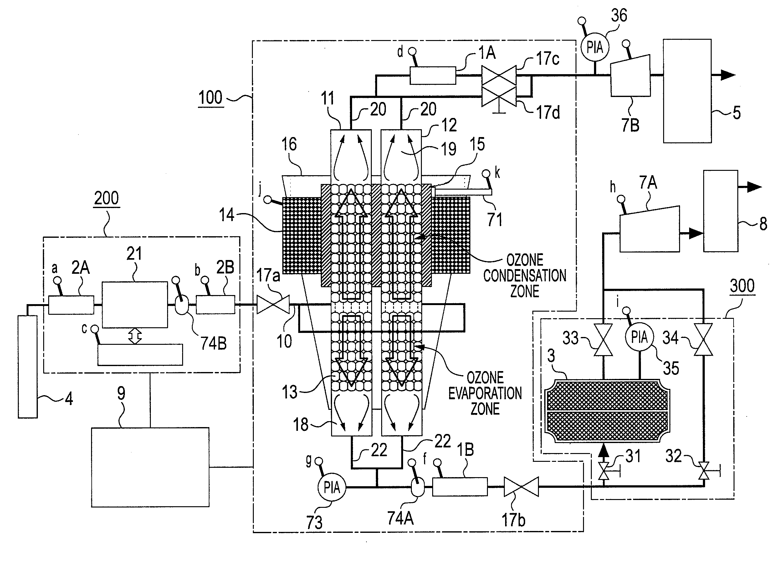
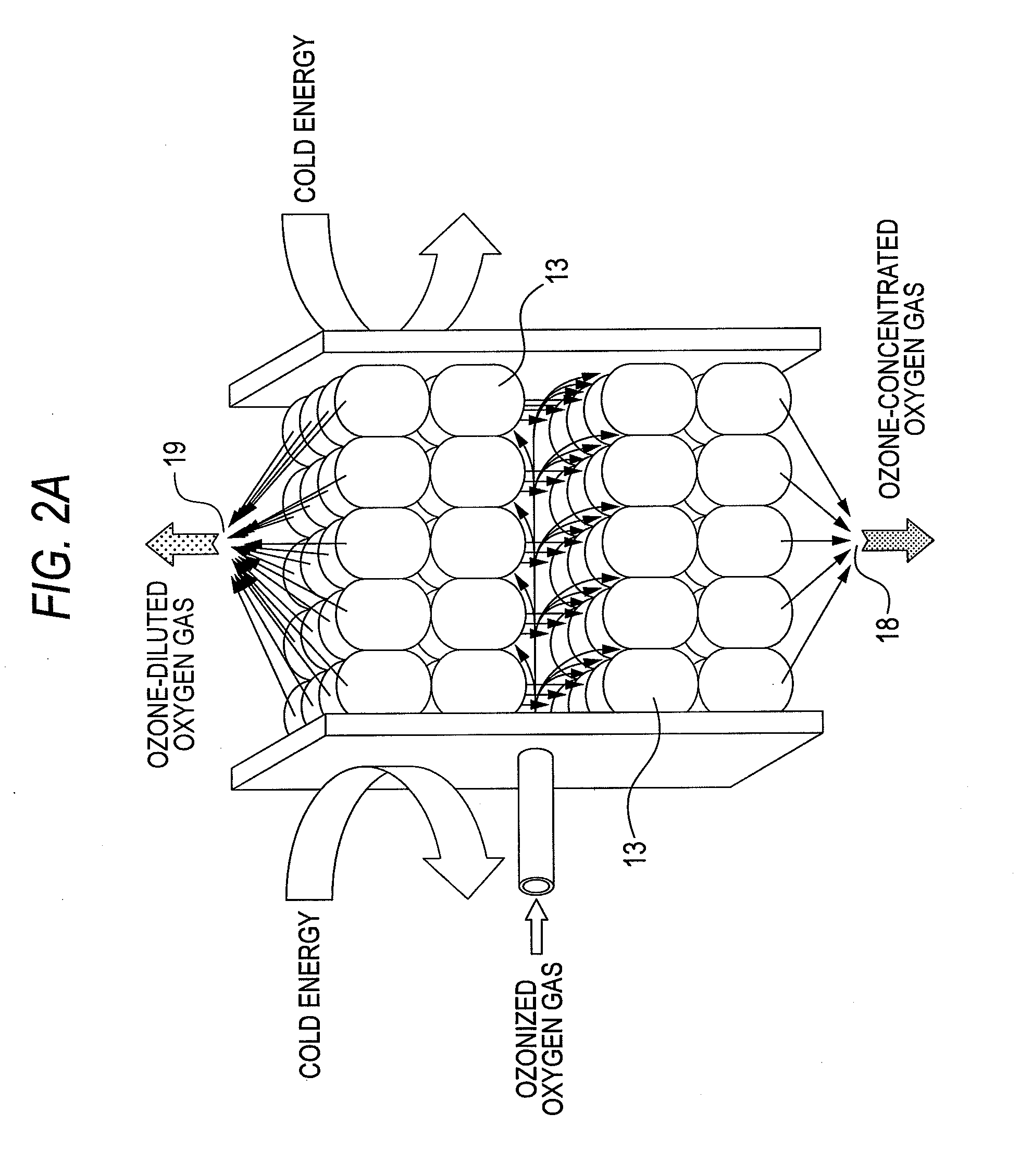
[0068]An embodiment 1 of the invention shows an example of an apparatus capable of selectively concentrating or diluting a specific gas (ozone gas) from a gas composition (oxygen gas and ozone gas) generated as an ozonized gas containing an ozone gas in a prescribed concentration in an oxygen gas with an ozone generator with an oxygen gas as a raw material gas. The embodiment 1 of the invention will be described with reference to FIG. 1, FIG. 2-a, FIG. 2-b, FIG. 2-c and FIGS. 4 to 6. FIG. 1 is a system block diagram of an ozone gas concentrating device showing the entire ozone concentrating system of the embodiment 1, in which an ozone gas as the specific gas is selectively condensed, and condensed ozone is vaporized (to an ozone gas). FIG. 2-a is a schematic illustration showing the principle of ozone concentration in the embodiment 1. FIG. 2-b is a characteristic diagram where the gases having ozone concentrated and ozone diluted are retrieved in the embodiment 1. FIG. 2-b shows, ...

embodiment 2

[0110]The embodiment 2 of the invention shows an example of an apparatus capable of selectively concentrating or diluting a specific gas (ozone gas) from a gas composition (oxygen gas and ozone gas) generated as an ozonized gas containing an ozone gas in a prescribed concentration in an oxygen gas with an ozone generator 200 with an oxygen gas as a raw material gas.

[0111]The embodiment 2 of the invention will be described with reference to FIGS. 7, 8, 9, 10 and 11. FIG. 7 is a system block diagram of an ozone gas concentrating device showing the entire ozone concentrating system, in which an oxygen gas as other gases than an ozone gas is selectively transmitted through a sheet in a thin membrane form to increase the ozone concentration in the ozonized gas, whereby the ozonized gas is concentrated. FIG. 8 is a schematic illustration showing the principle of ozone concentration in the embodiment 2. FIG. 9 is a schematic illustration of an ozone concentrating system, as an example, sho...

embodiment 3

[0148]An embodiment 3 shows a use example of the ozone concentrating system of the embodiments 1 and 2. FIG. 12 is a diagram showing comparison of concentrated ozone concentration characteristics with respect to the flow rate of the ozonized oxygen in the conventional concentrated ozone apparatus, and concentrated ozone concentration characteristics of an example of the invention, and FIGS. 13-a and 13-b are diagrams showing examples of single wafer type and batch type apparatuses, in which concentrated ozone of the invention is applied to formation of an oxide film in a semiconductor production apparatus. FIG. 14 shows vapor pressure characteristics of gas species contained in an ozone gas.

[0149]FIG. 12 shows the concentrated ozone concentration characteristics with respect to the flow rate (SCCM) of ozonized oxygen, in which the characteristic curve 2005 shows the ozone concentration characteristics by a conventional liquid ozone apparatus, and the characteristic curve 2006 shows ...


PUM

PropertyMeasurementUnit
pressureaaaaaaaaaa
temperatureaaaaaaaaaa

Abstract

One ozone concentrating chamber is provided therein with a part of a cooling temperature range where ozone can be selectively condensed or an oxygen gas can be selectively removed by transmission from an ozonized oxygen gas, and a part of a temperature range where condensed ozone can be vaporized, and condensed ozone is vaporized by moving condensed ozone with flow of a fluid or by gravitation to the part where condensed ozone can be vaporized, whereby the ozonized oxygen gas can be increased in concentration. Such a constitution is provided that a particle material 13 for condensation and vaporization filled in the ozone concentrating chambers 11 and 12 has a spherical shape of a special shape with multifaceted planes on side surfaces, or an oxygen transmission membrane 130 capable of selectively transmitting an oxygen gas in an ozone gas is provided.

Description

TECHNICAL FIELD[0001]The present invention relates to an apparatus and a method of selectively condensing only a specific gas or selectively transmitting other gases than a specific gas from a gas containing plural gas species, so as to concentrate or dilute the specific gas. In particular, it relates to an apparatus for concentrating and diluting a specific gas and a method therefor, in which by using only one chamber with a simple constitution without plural concentrating steps and retrieving steps, a specific gas is selectively condensed or other gases than the specific gas are selectively transmitted to form a diluted gas in a diluted gas retrieving part of the chamber, and simultaneously the condensed liquid is moved by gravitation to a concentrated gas retrieving part at a lower part of the chamber and is then gasified, so as to form a concentrated gas in the concentrated gas retrieving part of the chamber, whereby the concentrated gas and the diluted gas can be separately ret...

Claims


Application Information

Patent Timeline
Patent Type & Authority Applications(United States)
IPC IPC(8): F25J1/00
CPCB01D53/002B01D2256/14C01B13/0251C01B13/10C01B13/11C01B2201/80C01B2201/82C01B2210/0092Y02C10/10Y02C10/12Y02C20/40B01D5/00B01D53/22F25J3/06
Inventor TABATA, YOICHIROSAITSU, TETSUYAOKIHARA, YUJIROITOH, NOBUYUKIUEDA, RAYOHEITANIMURA, YASUHIROOHTA, KOJI
Owner TOSHIBA MITSUBISHI-ELECTRIC IND SYST CORP
Why Eureka
Try Eureka