Synchronous rectification type battery charging circuit and protection circuit thereof

Active Publication Date: 2008-05-08
SHENZHEN MINDRAY BIO MEDICAL ELECTRONICS CO LTD
View PDF2 Cites 7 Cited by
  • Summary
  • Abstract
  • Description
  • Claims
  • Application Information

AI Technical Summary

Benefits of technology

[0018]The advantageous effects of the prevent invention: the present invention introduces to the charging circuit a fast intelligent cutting-off circuit which can realize a real time detection for the input voltage, while the threshold value controlling the charging circuit is a fixed value slightly larger than the largest charging voltage of the battery. The charging circuit can be controlled in advance before the input voltage falls below the battery voltage, which makes switch tubes of the charging loop to be cut off fast, prevents the reflection of the voltage and the current of the battery and avoids a damage to the charging circuit and the battery, and greatly promotes the reliability of the charging circuit. The circuit of the present invention is simple in structures, has strong practicability, and has lower loss when it works which will not affect the charging efficiency.
of the prevent invention: the present invention introduces to the charging circuit a fast intelligent cutting-off circuit which can realize a real time detection for the input voltage, while the threshold value controlling the charging circuit is a fixed value slightly larger than the largest charging voltage of the battery. The charging circuit can be controlled in advance before the input voltage falls below the battery voltage, which makes switch tubes of the charging loop to be cut off fast, prevents the reflection of the voltage and the current of the battery and avoids a damage to the charging circuit and the battery, and greatly promotes the reliability of the charging circuit. The circuit of the present invention is simple in structures, has strong practicability, and has lower loss when it works which will not affect the charging efficiency.

Problems solved by technology

A too large short-circuit current will impair Q2 instantaneously, which thereby further cause impairments to Q1 and Q3.
If Q1˜Q3 are integrated inside the charging chip, it will directly damage the chip.
1) A diode or a control switch is inserted serially to the main loop of the charging circuit, as shown in the solution realized by D1 of FIG. 3 and FIG. 4, which prevents battery voltage reflection, however, this method lead to low efficiency due to a large positive voltage drop of the diode. In order to improve the efficiency, a MOSFET (i.e. Field Effect Transistor) is added in parallel to the anti-reflection diode. Although this method is reliable to accomplish cutting off the diode automatically, it cannot achieve high efficiency because of a high positive voltage drop of the diode, and it is difficult to make the miniaturization and modularization of the charging circuit because of the heating generated by the diode.
2) The method for comparing the battery voltage and the input voltage is applied. As shown in FIG. 5, when the input voltage is ΔV higher than the battery voltage and ΔV is less than 75 mV, the control circuit will enter to a sleeping mode in which the anti-reflection MOSFET and the charging circuit are cut off, and once ΔV is larger than 75 mV, the entire circuit will be waken up, wherein the anti-reflection MOSFET is turned on again and the synchronous rectification circuit keeps working. However, the battery voltage and the input voltage applied in this method are both floating voltage and the comparing threshold is only 75 mV. Since the battery voltage and the input voltage can not be judged correctly because the battery voltage and the input voltage both have ripple when they are working, and a sampling circuit of the battery voltage has certain delay, this method can not provide a effective cutting-off to the anti-reflection MOSFET and the charging circuit in time which makes it less reliable, thus to increase the risk that the anti-reflection MOSFET Q3 and the charging circuit are damaged. In practical, this risk increases with the increase of the number of the charged batteries that are connected serially.

Method used


Image

  • Synchronous rectification type battery charging circuit and protection circuit thereof
  • Synchronous rectification type battery charging circuit and protection circuit thereof
  • Synchronous rectification type battery charging circuit and protection circuit thereof

Examples


first embodiment

The First Embodiment

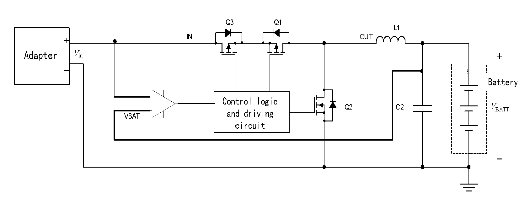
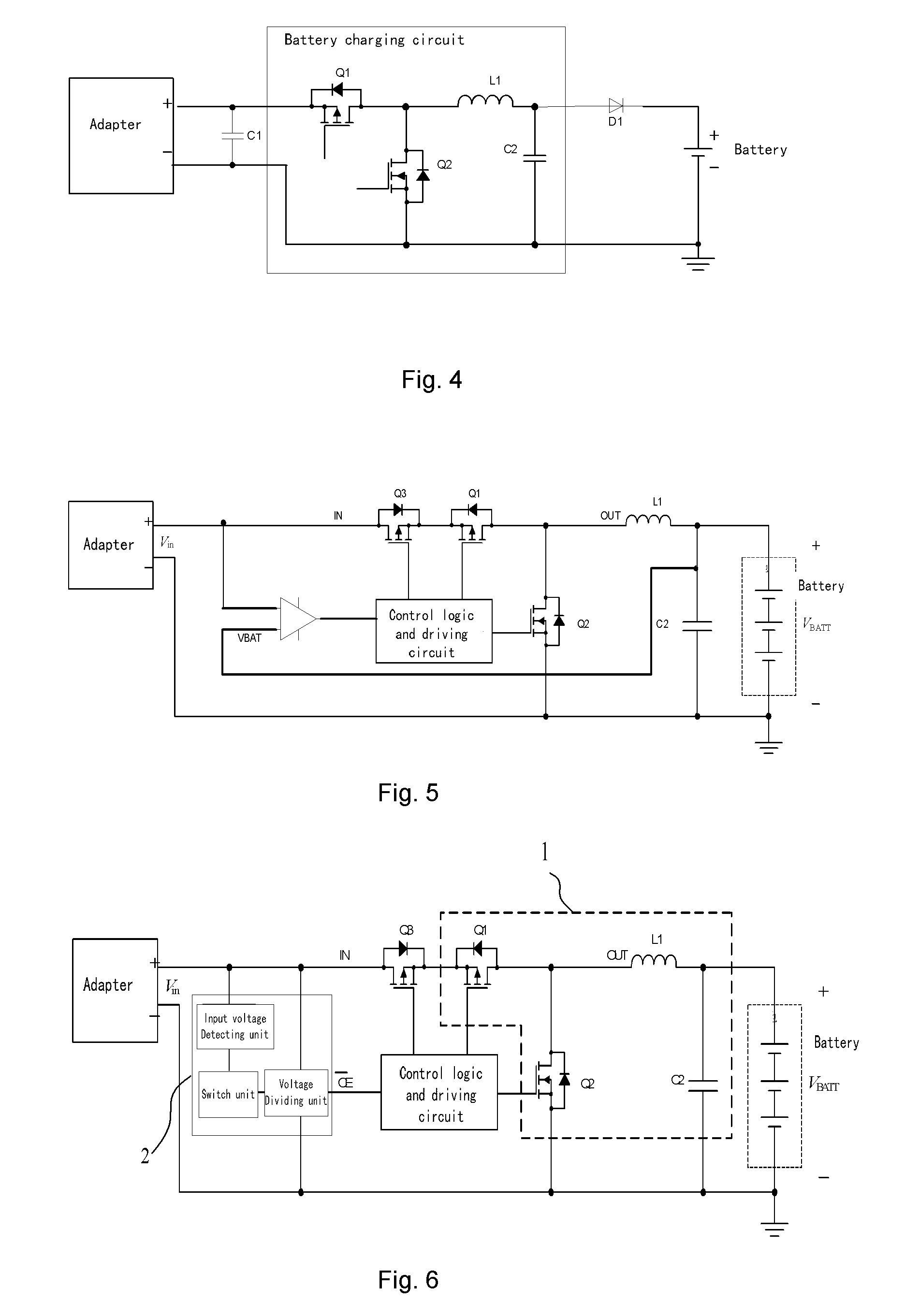
[0029]The synchronous rectification type battery charging circuit comprises a charging main circuit 1, an anti-reflection switch tube Q3, a control logic and driving circuit and a protection circuit 2. The an anti-reflection switch tube Q3 is connected between a power supply adapter and the charging main circuit 1, and the control logic and driving circuit generates a control signal to control turning-on and cutting-off of the charging main circuit 1 and the anti-reflection switch tube Q3. An implementation of the protection circuit is shown in FIG. 6. As shown in FIG. 6, with the maximal charging voltage VBATT-max of the charged battery as the initial detecting voltage value V1 and a predetermined margin V2 of the voltage sag or power-off of the battery charging circuit, by using a voltage detecting circuit whose detecting point is Vth=V1+V2, the protection circuit based on a switch device is formed, so that when the input voltage of the battery charging circuit...

second embodiment

The Second Embodiment

[0039]The protection circuit of the present invention also can be implemented by the method shown in FIG. 8. That is, the threshold voltage and the comparing and control program are first written into a microprocessor; after the input voltage detecting unit inputs to the microprocessor the input voltage detected in real time, the microprocessor then compares the detected input voltage with the threshold voltage, and outputs the corresponding high level or low level to the control logic and driving circuit according to the comparison result. The response and control method of the enable terminal of the control logic and driving circuit for high level and low level is the same as that of the first embodiment.

[0040]To sum up, the present invention can actively detect whether the input voltage of the battery charging circuit is power off, and automatically judge whether the input voltage arrives at a predetermined voltage. Moreover, the present invention has a chara...


PUM


Abstract

The present invention discloses a synchronous rectification type battery charging circuit, comprising: a charging main circuit for charging a battery; an anti-reflection switch tube, connected between a voltage input of the synchronous rectification type battery charging circuit and the charging main circuit; and a control logic and driving circuit, for controlling turning-on and cutting-off of the charging main circuit and the anti-reflection switch tube, characterized in that the synchronous rectification type battery charging circuit further including a protection circuit which outputs to the control logic and driving circuit an indicating signal for representing turning-on or cutting-off of the charging main circuit and the anti-reflection switch tube, according to a value of an input voltage of the synchronous rectification type battery charging circuit.

Description

TECHNICAL FIELD[0001]This invention relates to a battery charging circuit, and specially, to a synchronous rectification type battery charging circuit and its protection circuit.BACKGROUND OF THE INVENTION[0002]The chargeable lithium-ion battery has been used widely in portable devices. Currently, each large chip manufacturing company has its own dedicated lithium-ion battery charging chips to charge a lithium-ion battery formed by single or multi cells in series. Currently, most of the charging solutions use BUCK type topology, as shown in FIG. 1. The circuit has simple structure and high efficiency.[0003]To further improve the efficiency, synchronous rectification technology is more and more widely used in charging circuits. FIG. 2 is a BUCK type charging circuit using synchronous rectification technology. For the charging circuit of FIG. 2, the switch S1 and the diode D2 shown in FIG. 1 are replaced with MOSFET respectively, which effectively reduces a the on-state loss caused by...

Claims


Application Information

Patent Timeline
IPC IPC(8): H02J7/10
CPCH02J7/0031Y02E70/40Y02B40/90H02J7/0052H02J7/0029H02J7/00Y02B40/00Y02E60/10Y02E60/13
Inventor TANG, ZHIJIELI, GUANG
Owner SHENZHEN MINDRAY BIO MEDICAL ELECTRONICS CO LTD
Why Eureka
Try Eureka