Antenna cover for microwave ovens

Inactive Publication Date: 2008-05-08
TURBOCHEF TECH INC
View PDF89 Cites 66 Cited by
  • Summary
  • Abstract
  • Description
  • Claims
  • Application Information

AI Technical Summary

Benefits of technology

[0009] This object is achieved by providing an improved cove

Problems solved by technology

Contamination of the waveguide interior by such substances can reduce the life of the magnetro

Method used


Image

  • Antenna cover for microwave ovens
  • Antenna cover for microwave ovens
  • Antenna cover for microwave ovens

Examples


Embodiment Construction

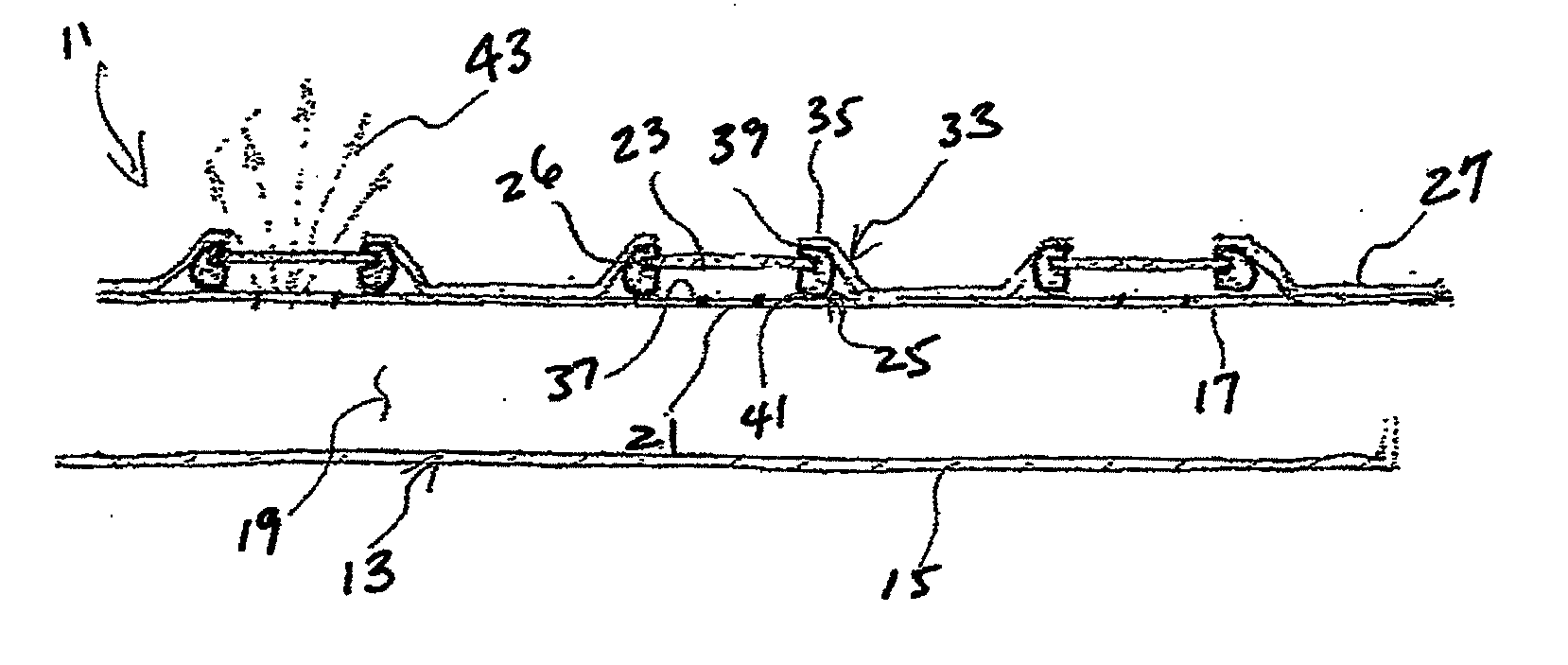
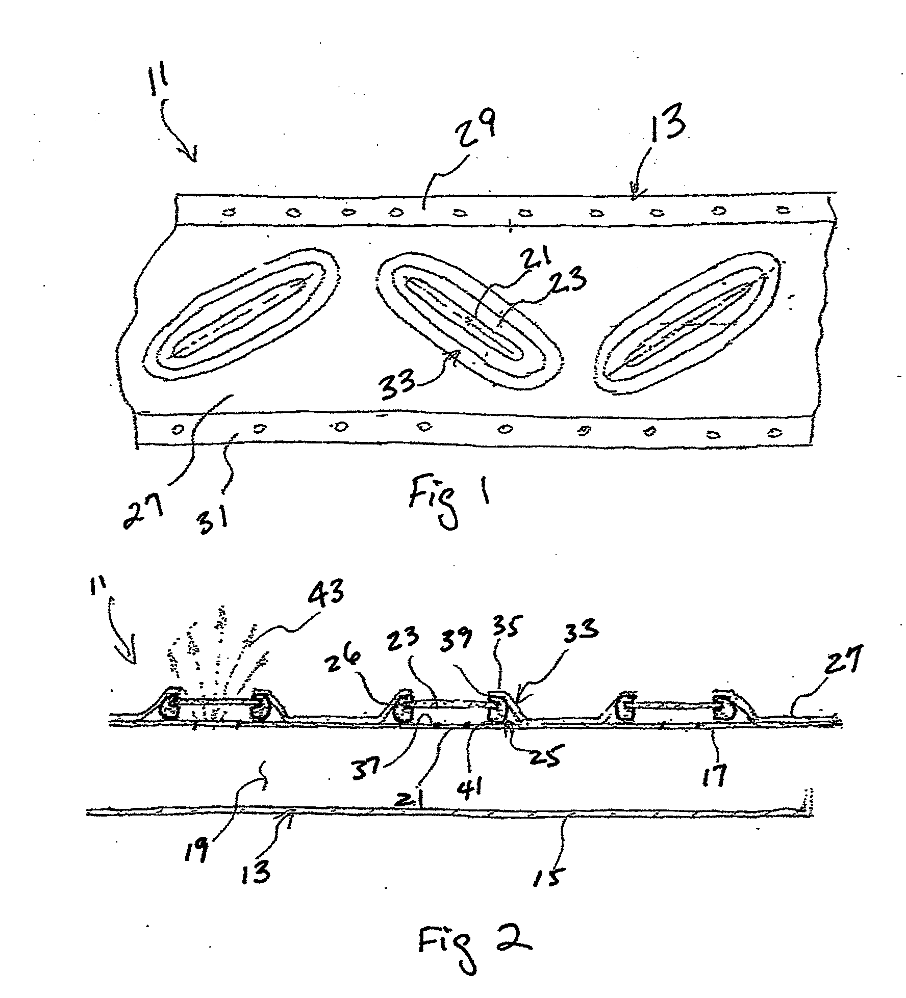
[0016] The present invention is directed to an improved antenna cover for ovens that operate using electromagnetic energy, such as microwave or radio frequency (RF) energy, emitted through slot antennas located in a high-temperature cook chamber, such as in a combination microwave and convection oven.

[0017] To reliably seal the slot antennas and associated waveguides while providing a low loss (E / H energy) interface to the cooking cavity, the present invention provides a very durable and low-cost cover for slot antennas. The cover plate material must be compatible with a high-temperature operating environment (such as the interior of a convention oven), must be of low-loss characteristics relative to microwave (or RF) transmission, easily cleaned, durable, and inexpensive. Suitable cover plate, or window, material can be either flexible or rigid. For good microwave compatibility, materials with a dielectric constant less than approximately 6.0 and a loss tangent less than approxima...


PUM


Abstract

An antenna cover assembly for a high-temperature operating environment has a cover plate, gasket portions, and a retainer plate. The cover plate has an inner side and an outer side, the cover plate being translucent to at least one selected frequency of electromagnetic energy. The gasket portions are each located adjacent one of the inner and outer sides, each gasket portion being configured for sealingly engaging the adjacent side. The retainer plate is configured for attachment to a structure located in a high-temperature operating environment. The retainer plate has a sealing flange adapted for clamping the cover plate generally adjacent an antenna portion of a waveguide.

Description

CROSS REFERENCE TO RELATED APPLICATIONS [0001] The present application claims priority to International Application No. PCT / US2005 / 035605 filed 5 Oct. 2005; claims priority to U.S. application Ser. No. 11 / 098,280 filed 4 Apr. 2005; claims priority to International Application No. PCT / US2006 / 009075 filed 14 Mar. 2006 and claims priority to U.S. application Ser. No. 11 / 392,050 filed 29 Mar. 2006. Upon entry into the National Stage in the United States of America, the present application will be a continuation-in-part of U.S. application Ser. No. 11 / 098,280 filed 4 Apr. 2005; will be a continuation-in-part of U.S. application Ser. No. 10 / 614,268 filed 7 Jul. 2003; will be a continuation-in-part of U.S. application Ser. No. 10 / 614,532 filed 7 Jul. 2003; and will be a continuation-in-part of U.S. application Ser. No. 11 / 392,050 filed 29 Mar. 2006. [0002] The present application contains technical disclosure in common with International Application No. PCT / US2003 / 021225 filed 5 Jul. 2003;...

Claims


Application Information

Patent Timeline
IPC IPC(8): H01Q1/42
CPCA21B1/245H05B6/6473H01Q1/42F24C15/325
Inventor MCFADDEN, DAVID H.BOLTON, DAVID A.
Owner TURBOCHEF TECH INC
Why Eureka
Try Eureka