Communication relay device, communication relay method, and computer product

a relay device and relay technology, applied in the field of communication relay devices, communication relay methods, and computer products, can solve the problems of deteriorating the quality of the traffic in the computer network, the bandwidth limitation of the input line, and the communication speed and accuracy of the packet transmission

Inactive Publication Date: 2008-05-08
FUJITSU LTD
View PDF4 Cites 21 Cited by
  • Summary
  • Abstract
  • Description
  • Claims
  • Application Information

AI Technical Summary

Benefits of technology

[0013]It is an object of the present invention to at least partially solve the problems in the conventional technology.

Problems solved by technology

However, when bandwidths of the connected lines differ, a bandwidth of an input line is subjected to a bandwidth limitation to output the packets to an output line.
However, carrying out the bandwidth limitation reduces the communication speed and accuracy of the packet transmission, thus resulting in a quality deterioration of the traffic in the computer network.
However, in the conventional technologies described above, when the traffic is monitored based on a quality control criterion which flexibly deals with the user's needs and the quality deterioration of the traffic is detected as a result of the monitoring, the quality deterioration is not notified to the user in real time and the user cannot take quick countermeasures.
Therefore, upon detecting that the quality of the traffic in a hierarchy has deteriorated, even if the QoS control system attempts to restore the quality of the traffic by automatically updating the communication parameters, the quality control itself is limited.
This is because a range subject to the quality control of the traffic is limited.
Further, in the latter conventional technology, although the user can freely set, according to his or her needs, the criterion that detects the quality deterioration of the traffic, the traffic control system does not notify the user of the detection of the quality deterioration in real time and the user cannot take quick countermeasures.
Further, even if these conventional technologies are combined, the quality deterioration related to the quality of a communication service is not notified to the user in real time according to the user's needs.
Thus, the user cannot take quick countermeasures.

Method used


Image

  • Communication relay device, communication relay method, and computer product
  • Communication relay device, communication relay method, and computer product
  • Communication relay device, communication relay method, and computer product

Examples


first embodiment

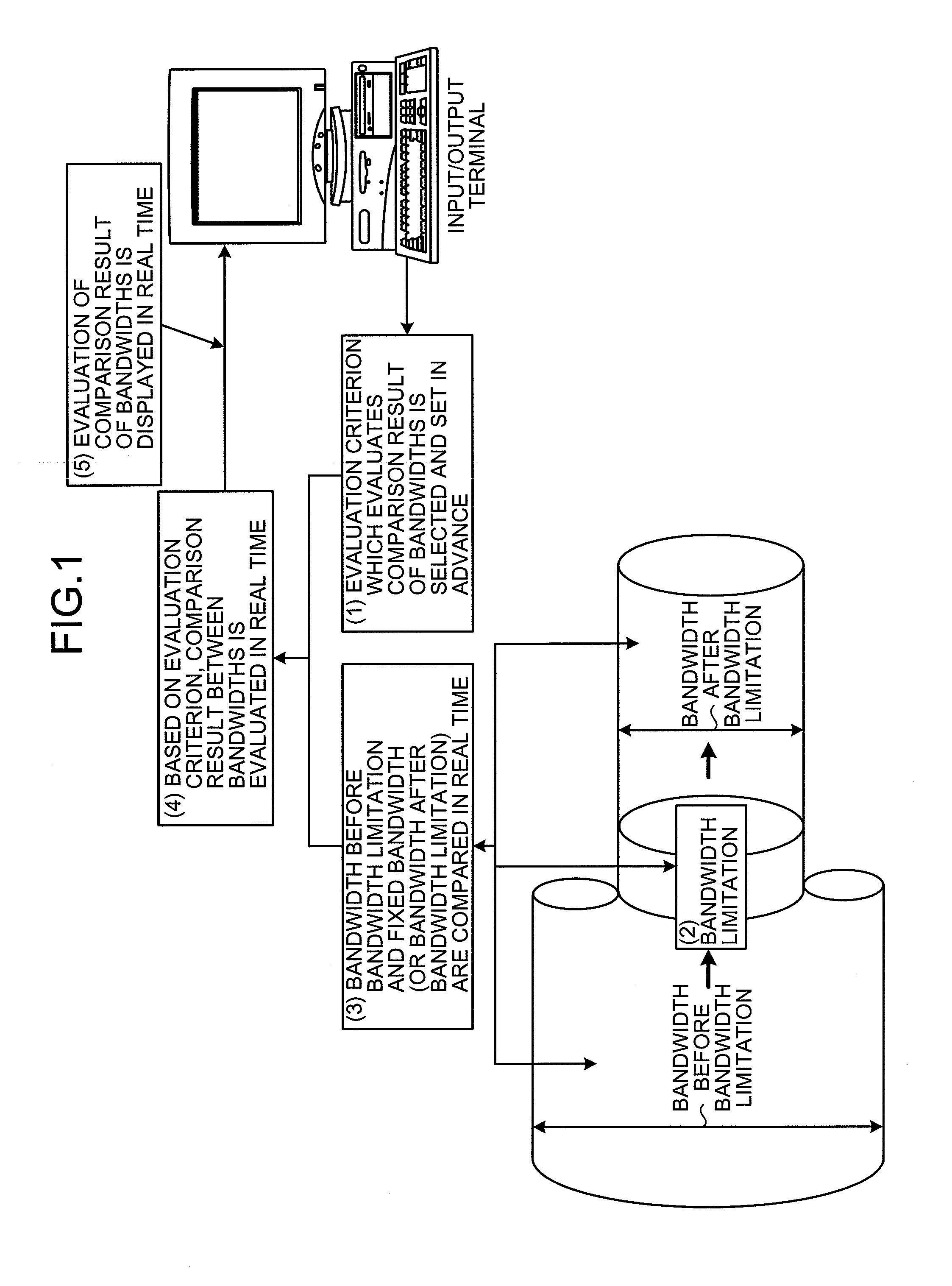
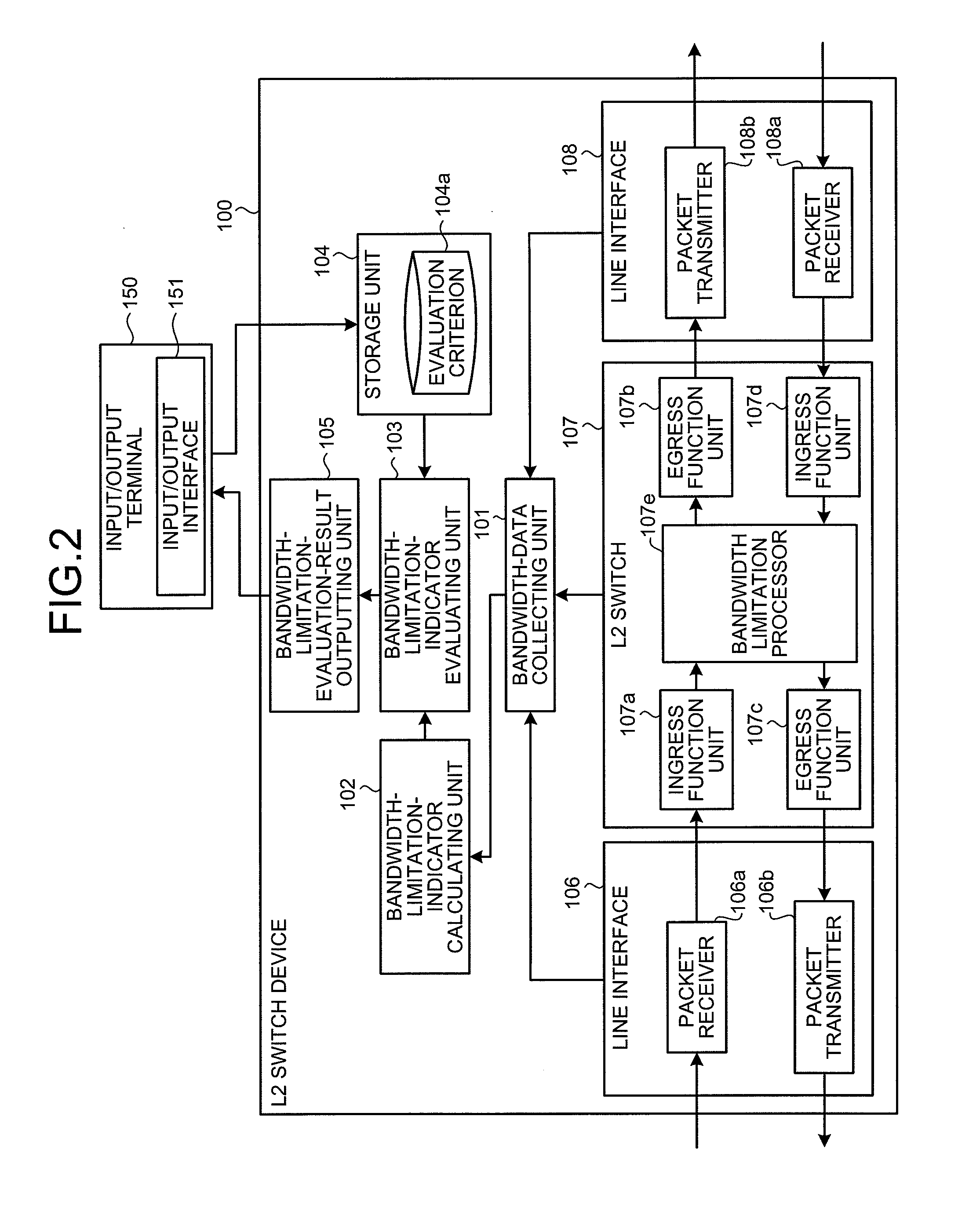
[0040]Based on the bandwidth data before the bandwidth limitation and the bandwidth data of the fixed bandwidth that are retrieved by the bandwidth-data collecting unit 101, the bandwidth-limitation-indicator calculating unit 102 calculates a bandwidth limitation indicator that indicates a degree of the bandwidth limitation. In the first embodiment, the difference between the bandwidth data before the bandwidth limitation and the bandwidth data of the fixed bandwidth is treated as the bandwidth limitation indicator. However, the present invention is not to be thus limited, and a difference between the bandwidth data before the bandwidth limitation and the bandwidth data after the bandwidth limitation, or a ratio of the bandwidth data before the bandwidth limitation and the bandwidth data after the bandwidth limitation can also be treated as the bandwidth limitation indicator. Thus, any indicator which can indicate a relation between bandwidths of the bandwidth data before the bandwi...

second embodiment

[0073]the invention is explained above. However, the present invention can be similarly applied to the relay and transferring process of the VLAN packet in the VLAN or the VPN packet in the VPN. When carrying out the relay and transferring process of data, the bandwidth-data collecting unit 101 retrieves the bandwidth data of the input packet and the bandwidth data of the output packet after the bandwidth limitation from the L2 switch 107 that processes the packets in VLAN units or VPN units. For example, the fixed bandwidth rate of X Mbps is stipulated for each VLAN that is identified by the VLAN ID and shaping (bandwidth limitation) is used to limit the input rate of W Mbps to the fixed bandwidth rate of X Mbps. When Z Mbps is the input margin rate, and X-W becomes less than Z, a notice is notified to the user. Further, similarly to the VLAN, the fixed bandwidth rate of X Mbps is stipulated for each VPN that is identified by a VPN identifier and shaping (bandwidth limitation) is u...

third embodiment

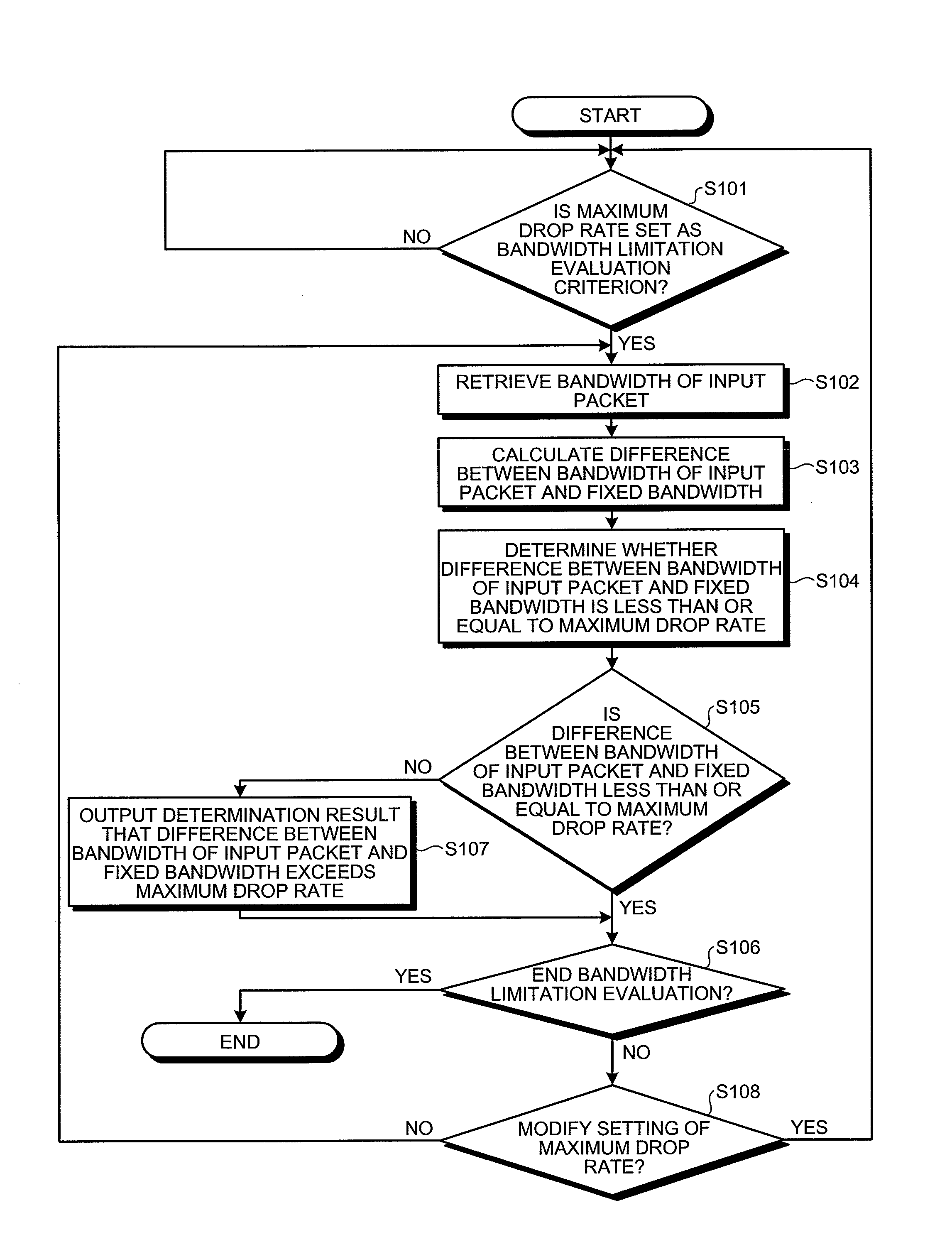
[0095]Thus, “MAXIMUM DROP RATE” is set for each user and “INDIVIDUAL STATUS” and “DROP RATE” according to the setting mentioned above are displayed for each user. Due to this, an occurrence of a defect in any user that the drop rate exceeds the maximum drop rate, can be clearly detected in real time, thus enabling the user to take quick countermeasures.

[0096]The first to the third embodiments of the present invention are explained above. However, the present invention is not to be thus limited, and various modifications may be made without departing from the spirit or scope of the general inventive concept as defined by the appended claims and their equivalents. Further, the effects described in the first to the third embodiments are not to be thus limited.

[0097]Using the communication relay device according to the present invention in a network structure enables to construct a network monitoring system that has easiness in use and high maintainability without necessitating a compl...


PUM


Abstract

An evaluation criterion that evaluates a comparison result of a bandwidth before a bandwidth limitation and a bandwidth after the bandwidth limitation is selected and set in advance in a layer 2 (L2) switch device according to the present invention. An input packet is subjected to the bandwidth limitation and then output. The bandwidth before the bandwidth limitation and the bandwidth after the bandwidth limitation are constantly compared. Next, based on the preset evaluation criterion, the comparison result of the bandwidths is constantly evaluated. The evaluation result is output in real time to an input/output terminal such that the evaluation result can be displayed. When the bandwidth that is limited via the bandwidth limitation exceeds a maximum value of an admissible packet-dropping bandwidth that is set in advance, the excess is notified to a user in real time and the user can take quick countermeasures.

Description

BACKGROUND OF THE INVENTION[0001]1. Field of the Invention[0002]The present invention relates to a communication relay device, a communication relay method, and a computer product that relay in a communication network, input data input from a line to another line as output data, and, more particularly to a communication relay device, a communication relay method, and a computer product that notify a quality deterioration of the communication network in real time and enable communication quality control by causing a user to take quick countermeasures.[0003]2. Description of the Related Art[0004]Recently, along with an increasing use of a computer network such as a local area network (LAN) and the Internet, a flow of traffic (traffic of packets) via a network line is also increasing.[0005]The computer network includes lines that are connected by a relay device. However, when bandwidths of the connected lines differ, a bandwidth of an input line is subjected to a bandwidth limitation t...

Claims


Application Information

Patent Timeline
Patent Type & Authority Applications(United States)
IPC IPC(8): G06F11/00H04L12/28H04L12/70H04L12/801H04L12/811H04L12/911
CPCH04L41/0896H04L47/10H04L43/16H04L43/0829
Inventor TOYOZUMI, YOKOMIYATA, SEIJIOGATA, YUMIKOSAKAMOTO, YOSHIKO
Owner FUJITSU LTD
Why Eureka
Try Eureka