Reception quality calculation method, reception quality calculation apparatus, and communication apparatus

Inactive Publication Date: 2008-05-08
FUJITSU LTD
View PDF14 Cites 12 Cited by
  • Summary
  • Abstract
  • Description
  • Claims
  • Application Information

AI Technical Summary

Benefits of technology

[0036] In light of the above, an object of this invention is to accurately calculate the HS-PDSCH reception quality, even when a fading environment prevails.
[0037] A further object of the invention is to accurately calculate the HS-PDSCH reception quality, even when a fading environment prevails, and to determine the CQI corresponding to this reception quality, and report the result to the transmitting apparatus.
[0040] A reception quality calculation method of this invention comprises a step of saving reception quality calculated in the past as a first reception quality, and of saving past CPICH symbols used in calculating the first reception quality; a step of performing channel compensation of the past CPICH symbols which have been saved using a current channel estimation value, and of calculating a second reception quality using the channel-compensated CPICH symbols; a step of determining the difference between the second reception quality and the saved first reception quality, as a reception quality correction value; a step of performing channel compensation of the current CPICH symbols using the current channel estimation value, and calculating a third reception quality using the CPICH symbols obtained; and a step of correcting the third reception quality using the correction value.
[0045] By means of this invention, HS-PDSCH reception quality can be accurately calculated even in a fading environment, and the CQI can be determined based on this reception quality and can be reported to the transmission apparatus, so that the transmission apparatus can transmit data at a transmission rate according to the HS-PDSCH reception quality; moreover, by means of this invention, the throughput of the communication system can be improved, without excessively high quality.

Problems solved by technology

As a result, the HS-PDSCH block error rate BLER is substantially lower than the stipulated value of 0.1; that is, quality is excessively high, and the communication system throughput characteristic is degraded.

Method used


Image

  • Reception quality calculation method, reception quality calculation apparatus, and communication apparatus
  • Reception quality calculation method, reception quality calculation apparatus, and communication apparatus
  • Reception quality calculation method, reception quality calculation apparatus, and communication apparatus

Examples


Embodiment Construction

[0062] (A) Reception Quality Calculation Processing of the Invention

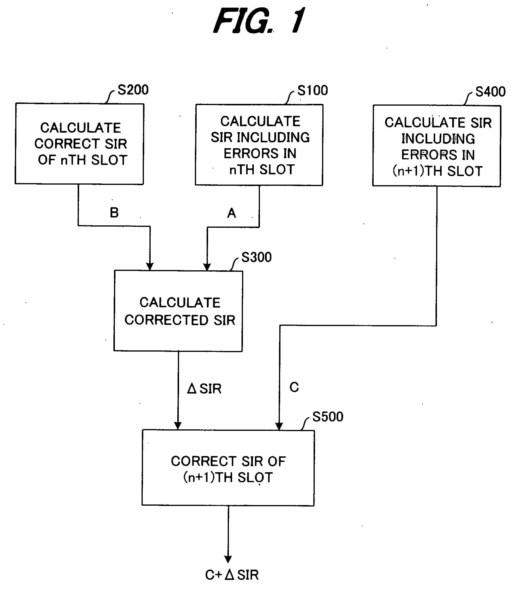
[0063]FIG. 1 shows in summary the processing flow of a reception quality calculation method of this invention.

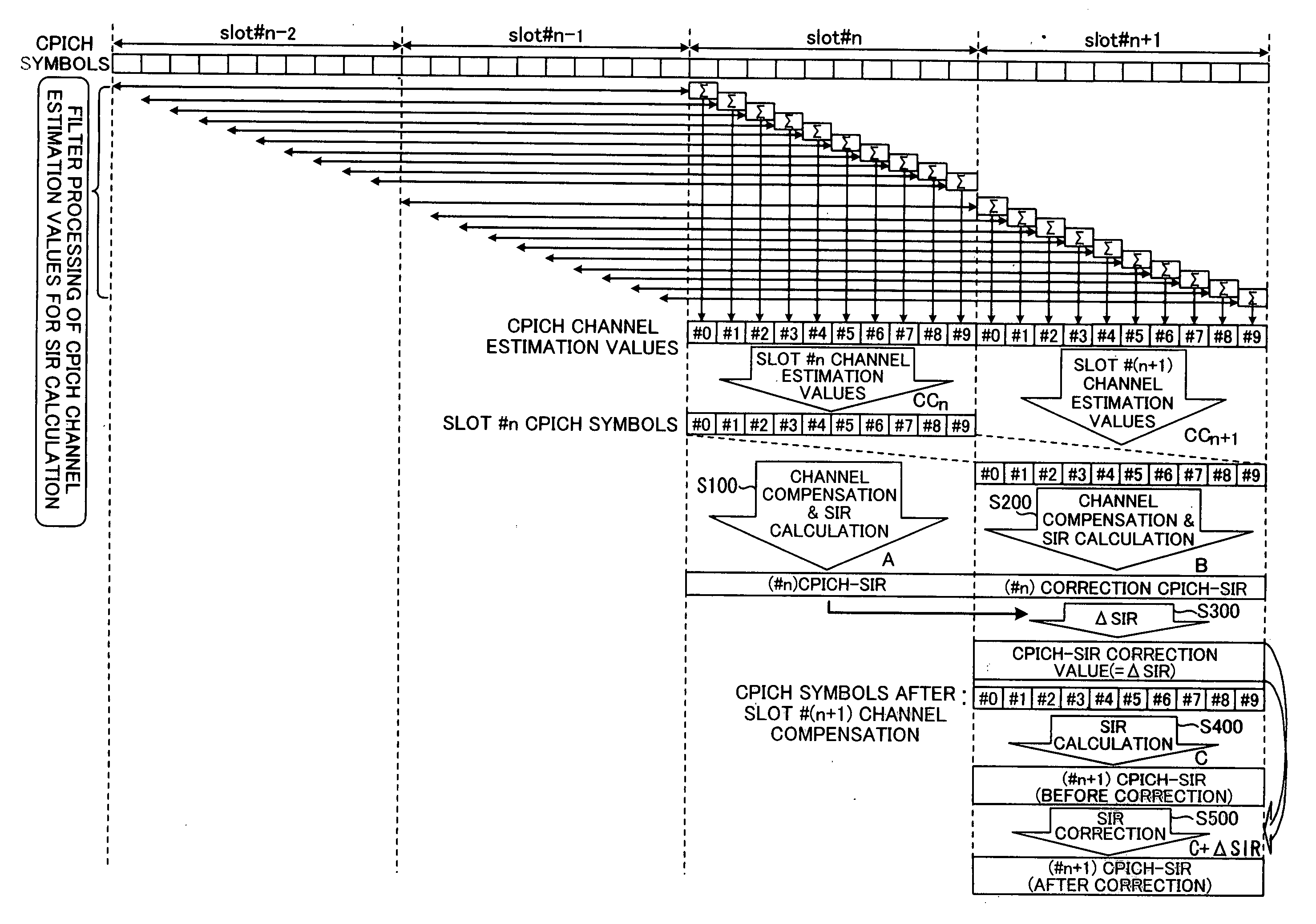
[0064] If reception quality, such as for example the signal-to-interference ratio (SIR) is measured with the slot period, then the reception quality (first reception quality) A including errors in the nth slot is calculated (step S100), the correct reception quality (second reception quality) B not including errors in the nth slot is calculated (step S200), and the difference between the first reception quality A and the second reception quality B is calculated as the correction SIR (=ΔSIR) (step S300). Then, the reception quality (third reception quality) C including errors in the (n+1)th slot is calculated (step S400), and the equation

SIR=C+ΔSIR

[0065] is used to correct the third reception quality C and output the result (step S500).

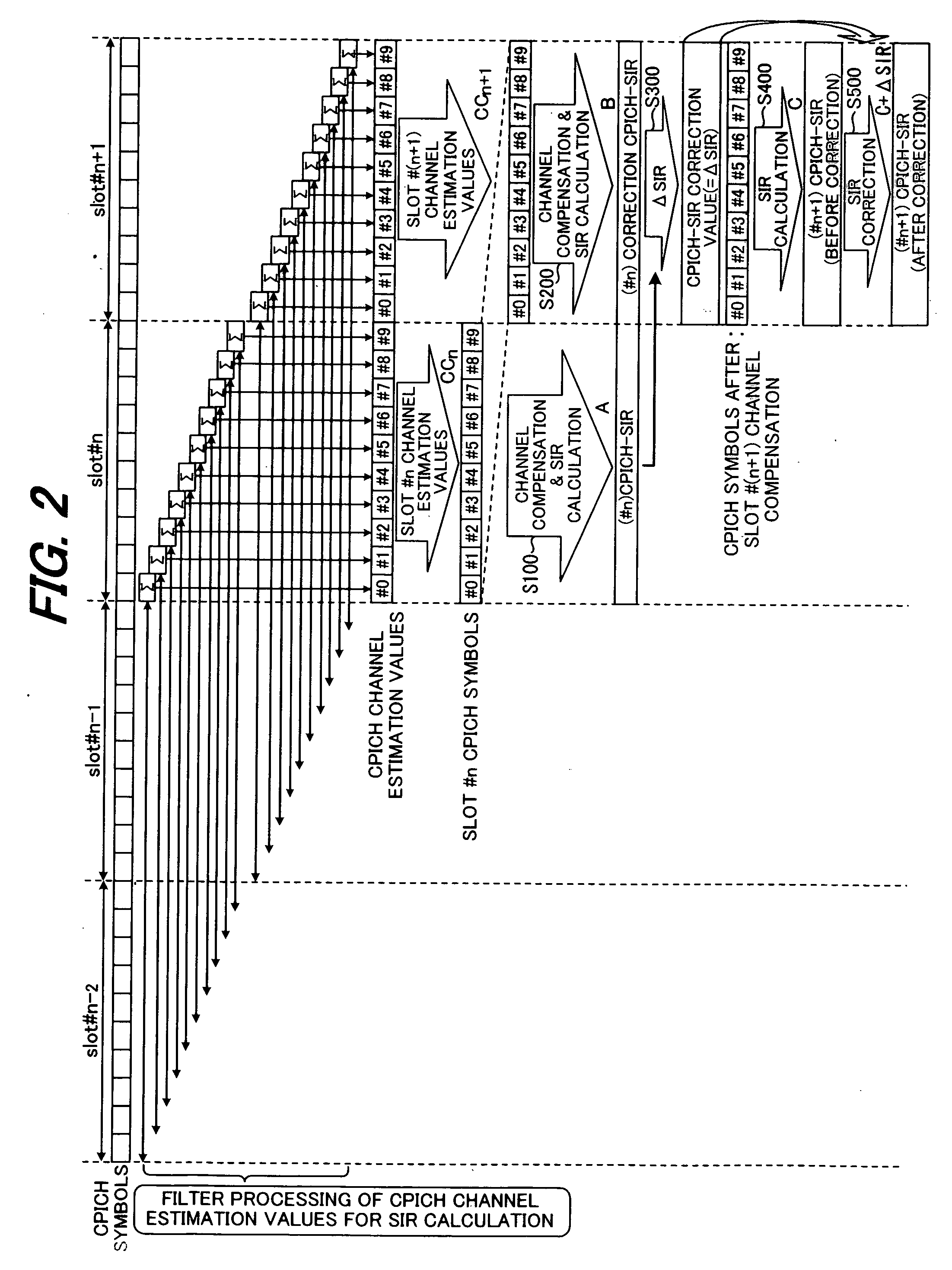
[0066]FIG. 2 explains reception quality correction processing of this...


PUM


Abstract

In a communication apparatus which transmits parameters corresponding to a reception environment to a transmitting apparatus which switches the transmission rate based on the reception environment, reception quality calculated in the past is saved as a first reception quality, and past CPICH symbols used in calculating this first reception quality are saved. Channel compensation of the saved past CPICH symbols is performed using a current channel estimation value, and the channel-compensated CPICH symbols are used to calculate a second reception quality; the difference between this second reception quality and the first reception quality is used as a reception quality correction value to correct reception quality.

Description

BACKGROUND OF THE INVENTION [0001] The present invention relates to a reception quality calculation method, a reception quality calculation apparatus, and to a communication apparatus, and in particular relates to a reception quality calculation method, a reception quality calculation apparatus, and to a communication apparatus in which reception quality is measured as a reception environment, and parameters (for example, CQI) corresponding to the reception environment are transmitted to the transmitting apparatus. [0002] A W-CDMA (UMTS) mobile communication system is a wireless communication system in which circuits are shared among a plurality of users, and as shown in FIG. 6, comprises a core network 1, wireless base station control apparatuses (RNCs: Radio Network Controllers) 2 and 3, multiplex separation apparatuses 4 and 5, wireless base stations (Node B) 61 to 65, and a mobile station (UE: User Equipment) 7. [0003] The core network 1 is a network used for routing within the ...

Claims


Application Information

Patent Timeline
IPC IPC(8): H04B1/10H04B1/711H04B1/707H04W24/00H04W76/00H04W76/02
CPCH04B1/712H04L1/20H04B2201/70701
Inventor NIBE, KEIJI
Owner FUJITSU LTD
Why Eureka
Try Eureka