Building, ventilation system, and recovery device control

a ventilation system and recovery wheel technology, applied in the field of ventilation system and recovery wheel, can solve the problems of reducing affecting the efficiency of ventilation system, so as to reduce the energy consumption of ventilation system, maintain purge effectiveness, and limit the carry-over of contaminants.

Active Publication Date: 2008-05-08
SEMCO INC
View PDF99 Cites 77 Cited by
  • Summary
  • Abstract
  • Description
  • Claims
  • Application Information

AI Technical Summary

Benefits of technology

[0025]In even another set of embodiments, the invention provides a building that includes at least one embodiment of the ventilation system, control system, or both described above, and the building may further include the at-least partially enclosed space described above in some embodiments. And in still another set of embodiments, the invention provides various methods of reducing energy consumption of a ventilation system, that involves utilizing a rotating recovery wheel to transfer at least one of heat and moisture between a return/exhaust airstream and an outside/supply airstream, and also involves utilizing and controlling at least one variable-speed drive system to vary a speed

Problems solved by technology

But adding or removing heat or humidity (moisture) typically involves the expenditure of energy.
As a result, the air that is contained within the transfer media, as it passes into the outside/supply airstream, may be substantially uncontaminated, clean air.
But problems have been encountered when variable air-volume systems have been used in conjunction with recovery systems and devices such as recovery wheel 10.
Specifically, applying energy recovery wheels and maintaining acceptable contaminant carry-over levels in variable air-volume systems has shown to be rather difficult due to changes in system pressures, airflows, or both.
Without a way to ensure effective purge operation, cross-contamination has resulted from 3% to as high as 20% of the exhaust air concentration for variable airflow systems incorporating energy recovery

Method used


Image

  • Building, ventilation system, and recovery device control
  • Building, ventilation system, and recovery device control
  • Building, ventilation system, and recovery device control

Examples


Embodiment Construction

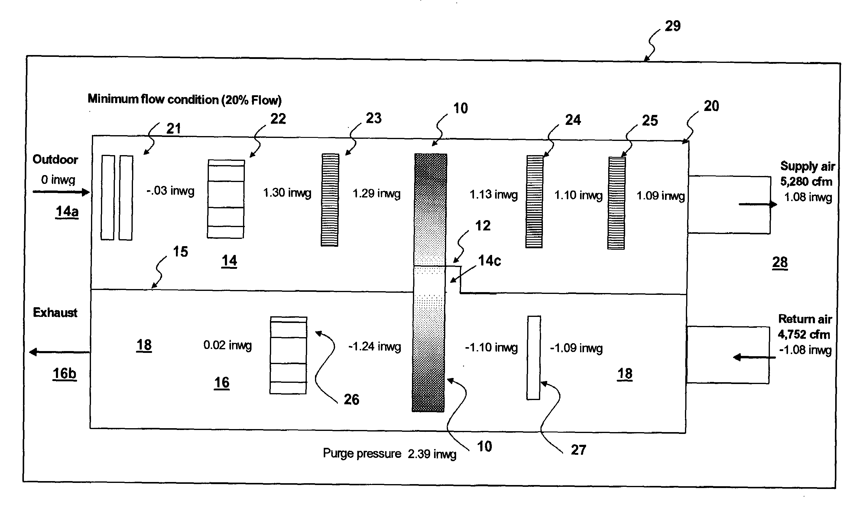
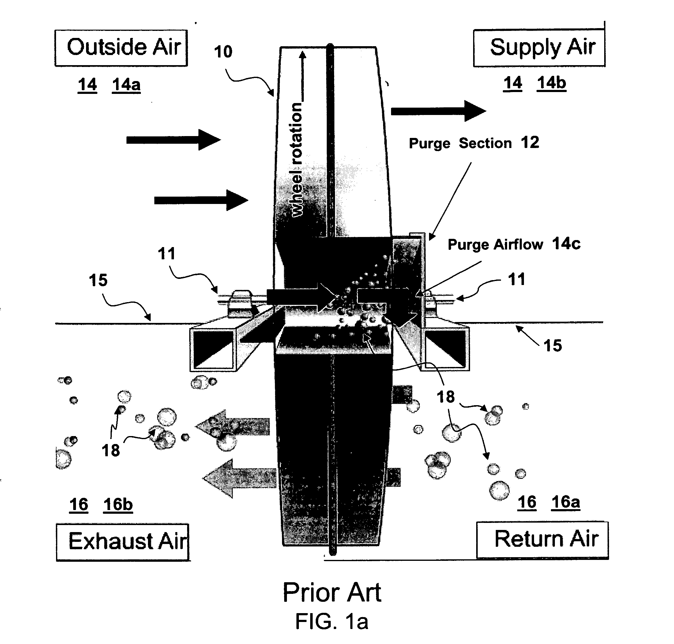
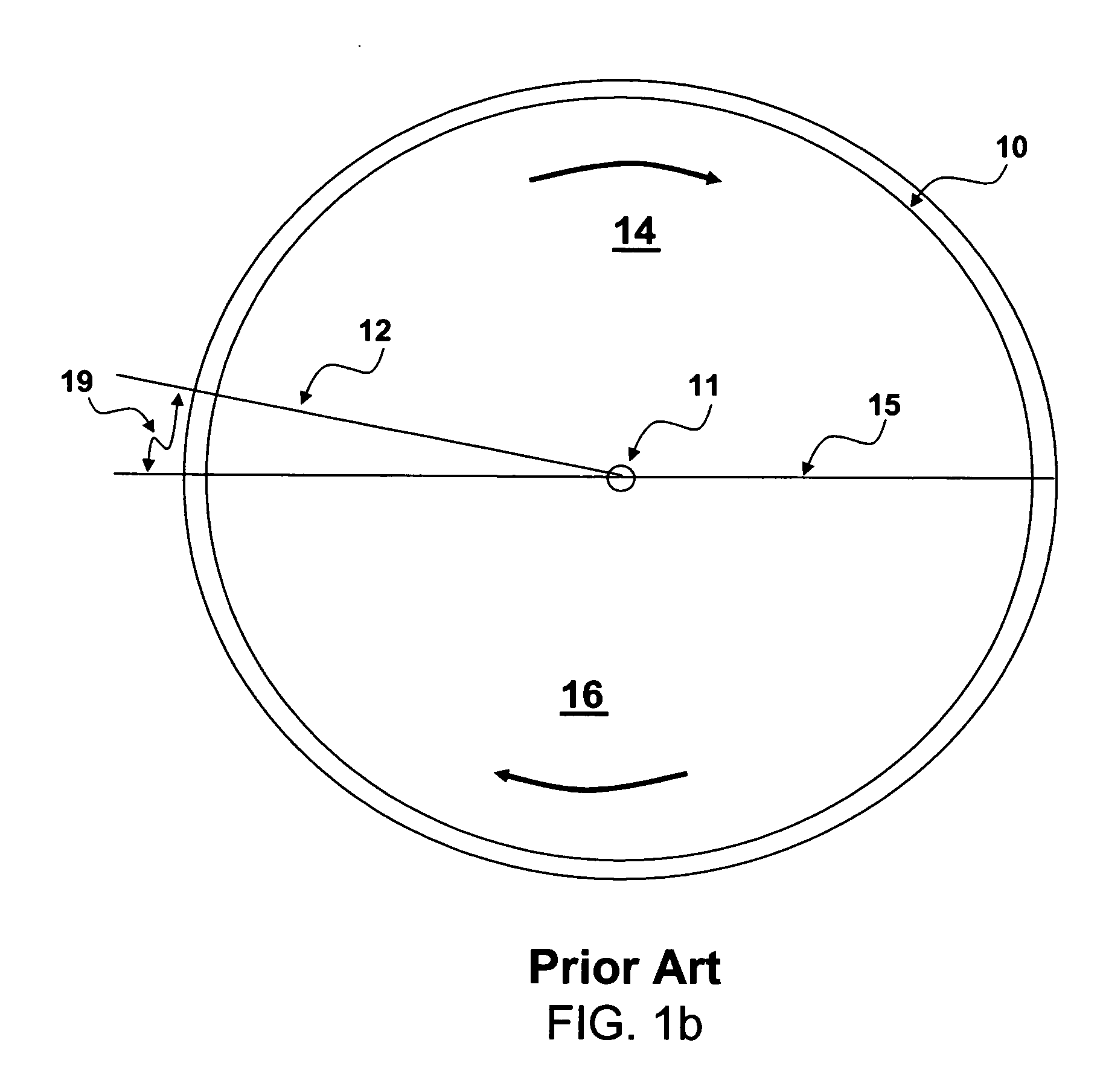
[0013]This invention provides, among other things, methods of controlling a recovery wheel in a ventilation system, methods of controlling a ventilation system to reduce energy consumption, methods of reducing energy consumption of a ventilation system, methods of modifying a ventilation system to reduce energy consumption, control systems for recovery wheels, ventilation systems for ventilating an at-least partially enclosed space, and buildings having certain ventilation systems.

[0014]Various embodiments of the invention provide as an object or benefit that they partially or fully address one or more of the needs, potential areas for improvement or benefit, or functions described herein, for instance. Specific embodiments provide as an object or benefit, for instance, that they at-least partially provide for control of recovery systems or devices such as recovery wheels, provide control of ventilation systems which may be new or existing systems, or provide ventilation systems or ...


PUM

PropertyMeasurementUnit
Timeaaaaaaaaaa
Temperatureaaaaaaaaaa
Pressureaaaaaaaaaa

Abstract

Control systems for recovery wheels, ventilation systems with recovery devices, buildings having ventilation, and methods of controlling recovery wheels and controlling or modifying ventilation systems. A parameter of ventilation systems or recovery devices, such as the speed of a recovery wheel, may be controlled as a function of pressure, differential pressure, flow rate, or fan speed, for example, to provide appropriate purge flow to maintain purge effectiveness and limit the carry-over of contaminants from a return/exhaust airstream to an outside/supply airstream, for instance, in a variable air-volume system. A purge angle may be set at a minimum position commensurate with a maximum flow rate and recovery-wheel speed may be reduced at lower flows to maintain purge effectiveness. In some embodiments, temperature and humidity are measured, and wheel speed is also controlled as a function of these measurements. Systems may utilize sensors, input devices, digital controllers, variable-speed drives, and alarms.

Description

FIELD OF INVENTION [0001]This invention relates to heating, ventilating, and air-conditioning (HVAC) systems and methods, buildings having such systems, and in particular embodiments, to ventilation and exhaust systems having recovery wheels, and controls for such systems.BACKGROUND OF THE INVENTION [0002]Heating, ventilating, and air-conditioning (HVAC) systems have been used to maintain desirable temperatures and humidity levels within buildings, and buildings have been constructed with ventilation systems including HVAC systems to provide comfortable and safe environments for occupants to live and work. To maintain fresh air within buildings and to reduce the level of indoor air contaminants, in many applications, at least a portion of the air handled by ventilation or HVAC systems has been taken from outdoors, while a portion of the indoor air handled by HVAC systems has been exhausted to outside the building. In many applications, particular sources of contaminants within build...

Claims


Application Information

Patent Timeline
IPC IPC(8): F24F11/00F24F3/14
CPCF24F3/1423F24F11/0079F24F2011/0042F24F2203/1004Y02B30/746F24F2203/104F24F2203/1068F24F2203/1088F24F2203/1096F24F2203/1032F24F2110/40F24F11/77Y02B30/70F24F11/00F24F3/14B01D47/00B01D53/14
Inventor FISCHER, JOHN C.BOLES, MICHAEL L.MITCHELL, RICHARD K.
Owner SEMCO INC
Why Eureka
Try Eureka